
Flow balancing intake manifold runners


Thread Starter
Junior Member
Joined: Oct 2003
Posts: 25
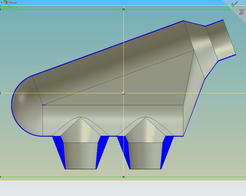
So the last intake manifold I used a symmetrical plenum so I wouldn't have to worry about any flow imbalances among the runners. I'm trying to make the new one with as long as runners as possible, so I'm going with a tapered side-feed design. I don't have access to a nice flowbench or anything, but then again I'm only trying to get a 50:50 flow ratio between the two runners.
I was thinking about perhaps using two flow/pressure gauges (the ones with a floating ball in a glass tube) in fittings that I could slip on the outlets of the velocity stacks, then hooking up a blower to the plenum inlet and changing the angle/internal geometry until the runners would each flow equally.
Think this would work? I was thinking I might have to use equally sized venturis/orifices in the fittings if I can't get enough velocity to get a pressure measurement. If anyone has any better ideas I would love to hear them! Also, anyone know the technical term for the floaty ball thingy? Pretty sad I can't remember after all these years slogging through engineering school...
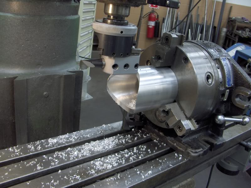
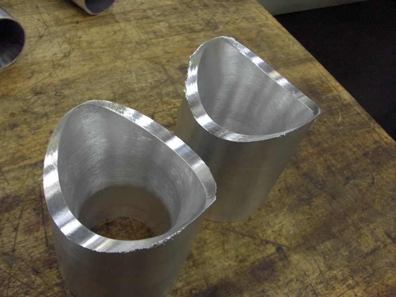
Here is a rudimentary drawing of the plenum in question, the geometry of the plenum will be changed somewhat from what is pictured but I already have the velocity stacks partially machined(ODs need cut and IDs will be finished after welding):

I was thinking about perhaps using two flow/pressure gauges (the ones with a floating ball in a glass tube) in fittings that I could slip on the outlets of the velocity stacks, then hooking up a blower to the plenum inlet and changing the angle/internal geometry until the runners would each flow equally.
Think this would work? I was thinking I might have to use equally sized venturis/orifices in the fittings if I can't get enough velocity to get a pressure measurement. If anyone has any better ideas I would love to hear them! Also, anyone know the technical term for the floaty ball thingy? Pretty sad I can't remember after all these years slogging through engineering school...
Here is a rudimentary drawing of the plenum in question, the geometry of the plenum will be changed somewhat from what is pictured but I already have the velocity stacks partially machined(ODs need cut and IDs will be finished after welding):

Fabricator

Joined: Jan 2004
Posts: 1,322
From: Central Ohio (Hebron) Zephyrhills Fla.
[quote name='LimitedSlip7' date='Mar 4 2008, 08:01 PM' post='895900']
So the last intake manifold I used a symmetrical plenum so I wouldn't have to worry about any flow imbalances among the runners. I'm trying to make the new one with as long as runners as possible, so I'm going with a tapered side-feed design. I don't have access to a nice flowbench or anything, but then again I'm only trying to get a 50:50 flow ratio between the two runners.
I was thinking about perhaps using two flow/pressure gauges (the ones with a floating ball in a glass tube) in fittings that I could slip on the outlets of the velocity stacks, then hooking up a blower to the plenum inlet and changing the angle/internal geometry until the runners would each flow equally.
Think this would work? I was thinking I might have to use equally sized venturis/orifices in the fittings if I can't get enough velocity to get a pressure measurement. If anyone has any better ideas I would love to hear them! Also, anyone know the technical term for the floaty ball thingy? Pretty sad I can't remember after all these years slogging through engineering school...
Here is a rudimentary drawing of the plenum in question, the geometry of the plenum will be changed somewhat from what is pictured but I already have the velocity stacks partially machined(ODs need cut and IDs will be finished after welding):
quote]
I'm 65 and have trouble remembering where I live. Hebron Ohio and Zephyrhills Florida.
One reason the stock plenum is so small is that it can be that small and still work. There is a natural line of thinking that this is a big engine and needs X amount of airflow at X RPM. Not the case. It is two little engines that share a plenum. So the combined airfflow amounts to quite a bit and that determines the TB size, where the two little engines start to look like a single big engine. The runner length in the stock engines (pre Renesis) are long enough to provide the needed torque at low speed. The engine is way over square and has a tiny stroke and is very low on low speed torque. So to get it usable in a car they had to work long and hard on low speed performance. The compromise then is not to hurt top end power too much.
Compromise is what the engine is made from, not aluminum and iron. Open the books and look at flow and friction. Drag increases at about the square of velocity. So smaller runners have better tuned effect, but slow total flow with increased drag. Bigger runners provide massive flow but loose tuned effect with low velocity.
Fuel injection near the port allows air without fuel to be managed effectively. In inline 4 cylinder engines the runners from the front cylinders face the runners from the rear cylinders across a plenum below the carb or TB. So the reflected wave from valve closing helps a bit with the apposing runner. Now with fuel injection at the port they have a log manifold like everyone else. Fuel air flow is far different than just air flow.
The little engines can ingest slightly more than their displacement In NA trim so that is the line of thinking (My reasoning) to work on. So if thats all that will go into the housing for each cycle then that volume is what to think about. The tuned effect amounts to getting a small additional amount of air to go into a space that is already full. So runner size near the port should be small to develop the highest possible velocity. Then taper from the port to the plenum, to reduce flow losses.
The plenum can be adjusted to be tuned to a different RPM range than the runners to help cover poor torque higher up. Typically the larger the volume the lower the tuned frequency. So modern plenums seem to look like log manifolds from the 50s and appear a bit small, in every case.
But if you have tapered runners the tune of the plenum will be mild indeed as reflected wave (Weak in Rotary) will be way behind the running RPM. Thus the small plenums and constant diameter runners of modern engines.
One idea is that your flow bench should have a shutter system to breath through to more accurately perform like a running engine. The shutter speed would replicate the engine RPM you are tuning for.
I suspect that Mazda and others have such a system.
One fast way to make runner changes and whole manifolds, is to build the runner from childs modeling clay. Just build it up from clay and make it smooth as silk. Let it dry for a few days and then paint it up with a mechanical epoxy (metal filled grey stuff. Then when that has set up, cover it with random glass cloth then build it up with glass cloth. Wrinse out the clay in solvent. The plenum part carve from styrene foam and cover with clay. You can make the TB mount right in the clay. Or place "T" nuts in the clay to hold studs. The runners are like glass inside. The manifold does not conduct heat. All is well. Easy to modify and manufacture.
Just some ideas.
Lynn E. Hanover

Senior Member
Joined: Feb 2005
Posts: 1,579
From: Kissimmee FL.
quick question to Lynn about the clay building manifold...
where can i get the "mechanical epoxy (metal filled grey stuff" you mentioned?
about this..."Then when that has set up, cover it with random glass cloth then build it up with glass cloth" do you mean fiber glass? if not where can i get this also?
and lastly, how do get the clay out from in side? you said rinse it out with solvent. so it just liquifies when the solvent hits it?
thanks...
Fabricator
Joined: Jan 2004
Posts: 1,322
From: Central Ohio (Hebron) Zephyrhills Fla.
Originally Posted by sen2two' post='895920' date='Mar 5 2008, 08:33 AM
quick question to Lynn about the clay building manifold...
where can i get the "mechanical epoxy (metal filled grey stuff" you mentioned?
about this..."Then when that has set up, cover it with random glass cloth then build it up with glass cloth" do you mean fiber glass? if not where can i get this also?
and lastly, how do get the clay out from in side? you said rinse it out with solvent. so it just liquifies when the solvent hits it?
thanks...
where can i get the "mechanical epoxy (metal filled grey stuff" you mentioned?
about this..."Then when that has set up, cover it with random glass cloth then build it up with glass cloth" do you mean fiber glass? if not where can i get this also?
and lastly, how do get the clay out from in side? you said rinse it out with solvent. so it just liquifies when the solvent hits it?
thanks...
You get a mechanical epoxy at a supply house like Fiber Glast inc. in Brookville Ohio. Just north of Dayton.FibreGlast@mail.vresp.com also random mat and cloth. laminating epoxy and if you like cheaper laminating styrene resin.
Solvent does dissolve the clay. You can rush it along with a cleaning brush. Lacquer thinner dissolves the styrofoam block inside the plenum.
LEH


Thread
Thread Starter
Forum
Replies
Last Post
alemmons
Rotary Engine Building, Porting & Swaps
1
Feb 11, 2010 04:09 PM
Liquid Anarchy
Rotary Engine Building, Porting & Swaps
12
Mar 31, 2006 06:21 PM
Jims5543
RX-7 & RX-8 Parts For Sale & Wanted
3
Jan 16, 2004 07:58 PM
Currently Active Users Viewing This Thread: 1 (0 members and 1 guests)