
exhaust porting opinions?


Thread Starter
Junior Member
Joined: Aug 2004
Posts: 20
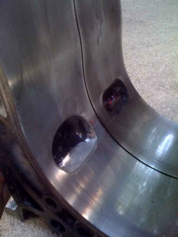
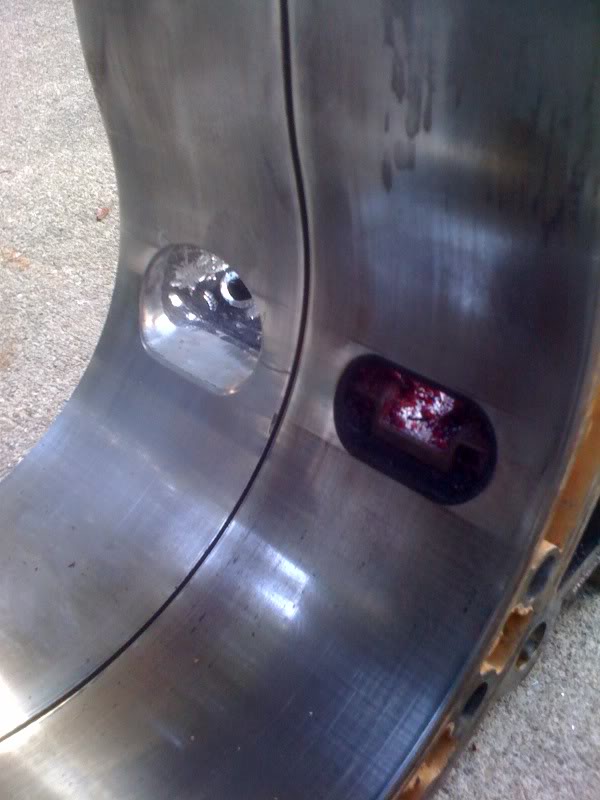
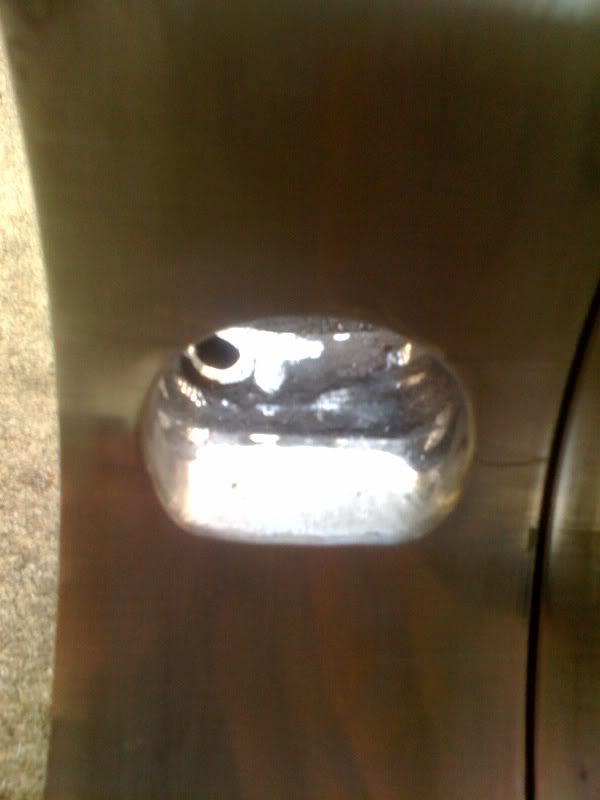
this is what i've come up with soo far. i was wondering what everyone thins of the shape and size of this port. Now i know theres no sleeve in this housing and this was just pratice and to let be able to make a template to transfer to my actual housings ill be using. thanks zack


Fabricator

Joined: Jan 2004
Posts: 1,322
From: Central Ohio (Hebron) Zephyrhills Fla.
this is what i've come up with soo far. i was wondering what everyone thins of the shape and size of this port. Now i know theres no sleeve in this housing and this was just pratice and to let be able to make a template to transfer to my actual housings ill be using. thanks zack


It would depend on what the engine will be used for. This is a big exhaust port. Road racer with best power between 8,000 and 9,500 RPM? Drag racer peaking at 10,500 RPM?
Turbo street rod with peak power at 7,500 RPM? Weekends only dyno racer?
The lack of an exhaust valve, the exhaust flow from a rotary is supersonic, and most of the combustion gasses are gone before the port is open 1/2 way. Early opening reduces torque, and the rotary has poor torque already. While many builders prefer the scooped center opening, it should be obvious that this will expose the center of the apex seal to higher heat for longer than the ends of the seal. The straight opening line does not do this to as great an extent.
The nearly empty chamber will be below ambient and assist the intake flow once some RPM have built up. But at low speed and inverse to back pressure, spent gasses will re-enter the chamber to reduce the intake charge and polute the intake charge. This reduces combustion temperatures, and helps HC and NOX but makes for a soft engine off idle. The taller the port (later closing) the more RPM before this problem stops, and the flow gets to be the right direction. In a Periphery port engine this is profound and obvious, less so in a side port engine. You might even find flow reversing at some speeds and gasses coming back into the chamber at the top of a tall port at some RPM. Depending on the reactor and muffler combinations.
All of these grinding operations affect idle and low RPM operation. When you a cruising along on the freeway, check the RPM. Not much RPM is it. So you take away that 14 to 18 HP you need to go 65 MPH and move it up the RPM band. So now you need more throttle to go 65 MPH, and that means low fuel mileage.
Here is a old Madeville housing that could make over 300 HP in a 12-A. Not a very exotic exhaust port is it? Notice the flat open and closing lines. Since this is a Pport, the connection between the intake and exhaust during overlap is very strong, so little changes in the exhaust port have a big effect. Most of the ports from similar engines, and from Daryl Drummond engines look like this. These engines had almost no muffling, so low speed dilution was not a factor.
This is all for NA stuff, and once the boost is up, it is of little help in a turbo engine.
So, what is it for? Is it a turbo engine? and so-on.
Lynn E. Hanover
Thread Starter
Junior Member
Joined: Aug 2004
Posts: 20
its a 13b-re motor with a t67. the car is mainly going to be used for autox and spirited driving. like i said this was just a rough draft to get an over all shape to make a template. its based off pineapples ep3a template.
so what should i do to change the port i have. bring in the closing a little earlier?
thanks for your help and anymore would be greatly appreciated.
zack.
so what should i do to change the port i have. bring in the closing a little earlier?
thanks for your help and anymore would be greatly appreciated.
zack.
Fabricator
Joined: Jan 2004
Posts: 1,322
From: Central Ohio (Hebron) Zephyrhills Fla.
its a 13b-re motor with a t67. the car is mainly going to be used for autox and spirited driving. like i said this was just a rough draft to get an over all shape to make a template. its based off pineapples ep3a template.
so what should i do to change the port i have. bring in the closing a little earlier?
thanks for your help and anymore would be greatly appreciated.
zack.
so what should i do to change the port i have. bring in the closing a little earlier?
thanks for your help and anymore would be greatly appreciated.
zack.
Well that's completely different.
Turbo engines use boost to make up for poor side port breathing. Exhaust ports can be opened a bit early to help the turbo come on sooner. Boost make the engine bigger by packing in the volume of mixture than the actual displacement of the engine. As you would expect, this improves the HP available from smaller engines like rotaries (2606 CCs). Boost can overcome some really bad porting choices. Too early or too late just needs more boost to get it back.
When you get further up in HP, you need to have your own dyno or copy pieces (port timing) from known performers. Exhaust flow in a turbo is far more complex a subject than in the NA engine.
The turbo sits close by the exhaust ports and presents a major back pressure generator. There is also the fact that there is much more exhaust gas to deal with. Here is a start on the subjects.
You need a large diameter degree wheel and a dial indicater with magnetic base. Read about finding TDC and you can lay out any port you can recover the timing for.
Lynn E. Hanover
Port Timing Basics
written by Paul Yaw at YawPower
After a great deal of thought, I decided that this first article should cover the basic workings of the rotary engine. In my experience, most people have the hardest time understanding port timing, and how it relates to engine operation. The accompanying illustration from "The Rotary Engine" by Kenichi Yamamoto will make this much easier to understand. At first, it may seem a bit confusing, but if you simply follow the numbers in order it is actually quite simple.
Before going into detail, it is critical that the reader understand some basic terminology. The various timing events of an internal combustion engine are typically stated in degrees of crankshaft rotation. In our case, output shaft, or eccentric shaft rotation. This terminology comes from the piston engine. Top dead center, or TDC refers to the working chamber being at its smallest possible volume. In a reciprocating piston engine, this occurs when the piston is at the very top of its stroke, hence the term top dead center. Bottom dead center, or BDC refers to the chamber being at its largest possible volume. In a reciprocating piston engine this occurs when the piston is at the very bottom of its stroke. All chamber volumes between TDC, and BDC, are referred to as Before TDC (BTDC), after TDC (ATDC), before BDC (BBDC), and after BDC (ABDC). For instance, 45� ATDC refers to the point at which the eccentric shaft has rotated 45� beyond top dead center. This is the situation in the first picture, looking at the chamber numbered 1. The line in the center of the picture extending from the crosshairs illustrates the angle of the eccentric shaft. This line corresponds with the keyway in the front of the shaft.
Below is a description of the complete process. Each description corresponds to the number in the illustration.
1. 45� ATDC The intake stroke is just beginning. The exhaust port has just closed, and on a stock or street ported engine, the intake port has been open for approximately 15�.
2. 90� ATDC The intake port is almost completely open, and the chamber is starting to expand at a fairly rapid rate.
3. 180� ATDC The intake port is all the way open, and has just passed the point of maximum flow. Maximum flow occurs at approximately 135� ATDC, which corresponds with the maximum rate of chamber volume increase.
4. BDC of the intake stroke. The intake chamber is now at its largest possible volume. The intake port is partially open, and the port is still flowing in the forward direction, even though the chamber is no longer increasing in volume. This is due to the inertia of the column of air flowing in the induction system. This effect is referred to as inertial supercharging, and is described in further detail in the airflow section of my webpage. This will also be addressed in a later article.
5. 45� ABDC The chamber has started to decrease in volume, and with the exception of a stock US model 12A, which has an intake port closing of 40� ATDC, the intake port is still partially open. At high rpm, the intake port is still flowing in the forward direction due to inertial supercharging. At low rpm, airflow in the port has reversed, and some of the intake charge is being squeezed back into the induction system by the pressure of the intake chamber which is decreasing in volume. This is the result of the low velocity in the induction system. This is a very important point to consider, as this alone affects the operating range of the engine more than any other factor.
6. 90� ABDC The intake port is completely closed, and air fuel mixture is being compressed.
7. 135� ABDC Same as #6.
8. 180� ABDC More of the same.
9. TDC of the compression stroke. The mixture is fully compressed, and ignition has started.
10. 90� ATDC The expansion cycle has started, and is already 45� past the point of maximum torque transfer to the eccentric shaft, which occurred at 45� ATDC.
11. 135� ATDC The expansion stroke continues, but the torque transferred to the output shaft is now down to about 35% of its peak.
12. 180� ATDC The exhaust port is still closed, and the torque transfer to the eccentric shaft is approximately 15% of its peak.
13. 225� ATDC At this point, the exhaust port has been open for approximately 30�, and exhaust flow is quite high.
14. BDC of the exhaust stroke. This is typically the point of maximum flow through the exhaust port. Even though the chamber volume is not decreasing at an appreciable rate, the chamber pressure is very high, and this is responsible for a large percentage of the total exhaust flow.
15. 90� ABDC The chamber volume is decreasing, and is 45� away from the point of maximum rate of decrease of the chamber volume.
16. 180� ABDC The exhaust chamber volume continues to decrease, and at approximately this point, a bridge ported, or peripheral ported engine will have started to open the intake port.
17. 225� ABDC The exhaust port is still open, and the chamber volume is decreasing at a relatively slow rate. At this point, a mildly bridge ported engine will have just opened the intake port.
18. TDC of the intake stroke. Here we are at the beginning, ready to start all over again. Note that the exhaust port is still open, but the intake port, for a non bridge ported engine has not opened yet.
I have included the port timing for all RX-7 engines, and some alternative ports, so that you can make comparisons, and gain a greater understanding of how the rotary engine operates.
This information may seem very basic to some readers, but it is critical to the understanding of performance tuning. As most of you know, changing the port timing of the rotary engine can result in large horsepower gains. Further articles will discuss this in detail, and without this knowledge base, the upcoming articles will make very little sense.
Next months article will cover the exhaust cycle, and its effect on engine performance and efficiency.
Paul Yaw.
Port Timing
IO = Intake opens
IC = Intake closes
EO = Exhaust opens
EC = Exhaust closes
US Model First Generation RX-7
IO 32� ATDC
IC 40� ABDC
EO 75� BBDC
EC 38� ATDC
European Model First Generation RX-7
IO 32� ATDC
IC 50� ABDC
EO 75� BBDC
EC 48� ATDC
First and Second Generation 6-Port 13B
Primary intake (Part throttle/cruise)
IO 32� ATDC
IC 40� ABDC
Secondary intake (Part to full throttle)
IO 32� ATDC
IC 30� ABDC
Auxiliary high speed ports (Full throttle above approximately 4000 rpm)
IO 45� ATDC
IC 70� ABDC
EO 71� BBDC
EC 48� ATDC
Second and Third Generation Turbo 13B
IO 32� ATDC
IC 50� ABDC
EO 71� BBDC
EC 48� ATDC
Racing Beat "Street Port"
IO 25� ATDC
IC 60� ABDC
EO 84� BBDC
EC 48� ATDC
Racing Beat "J-Bridge Port"
IO 115� BTDC
IC 72� ABDC
EO 88� BBDC
EC 57� ATDC
Mazda Factory Peripheral Port
IO 86� BTDC
IC 75� ABDC
EO 73� BBDC
EC 65� ATDC
Thread Starter
Junior Member
Joined: Aug 2004
Posts: 20
thanks for that, but it's a little over the scope for this build. im not looking to sqeeze every ounce of power out of this motor. just looking to open up the ports while i have it apart. i guess i'll prob just order pineapples templates.

Member
Joined: May 2005
Posts: 37
If you're not really into the basics of port timing and their effects on powerbands, etc., then one thing is very important that you should know: Taking a die grinder to the housings or the irons will not necessarily improve flow, power, or give you power where you want it. If you stick to RB or other proven streetport templates (for both intake and exhaust) you will be OK, as they are only minor changes.
And, like mentioned on the "other" forum, it is very advisable to keep the exhaust inserts (Turbo ones), and not to port beyond them. They are useful, and going further than them in a street application does not really give you any more favourable results.
And, like mentioned on the "other" forum, it is very advisable to keep the exhaust inserts (Turbo ones), and not to port beyond them. They are useful, and going further than them in a street application does not really give you any more favourable results.

Senior Member
Joined: May 2002
Posts: 22,465
From: California
then you really should just open up the primary port to FD spec and leave it alone. its much simpler to just use stockish ports that actually work vs some big giant experiments.
besides its a turbo, the power isn't in the ports, its in the turbo.

Thread
Thread Starter
Forum
Replies
Last Post
Ariel
Rotary Engine Building, Porting & Swaps
13
Nov 18, 2005 02:45 AM
Danno
Rotary Engine Building, Porting & Swaps
6
Mar 6, 2003 01:35 AM
Currently Active Users Viewing This Thread: 1 (0 members and 1 guests)