4 Rotor Build in Sweden
 09-24-2011, 04:02 AM
#91
Senior Member
Thread Starter

Join Date: Sep 2003
Posts: 229
I have now google-translated to explain myself 
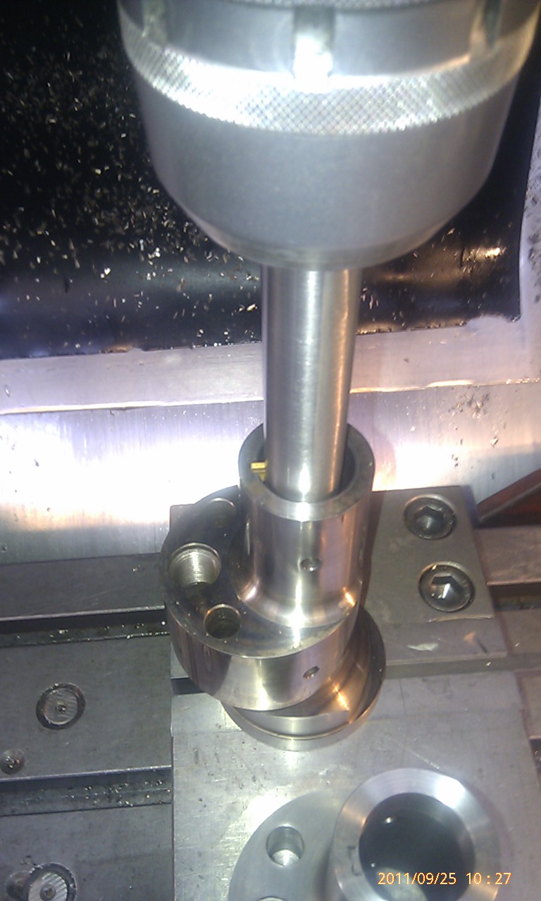
This tool I will put into my CNC-mill. Lock the spindel still. Then I will "shave" of the material inside the lose shaft-parts to make the KEYWAY
Yesterday the word "keyway" wasn't in my head, soo I used the word jack
This tool I will put into my CNC-mill. Lock the spindel still. Then I will "shave" of the material inside the lose shaft-parts to make the KEYWAY
Yesterday the word "keyway" wasn't in my head, soo I used the word jack
 09-25-2011, 03:34 AM
#92
Senior Member
Thread Starter
Join Date: Sep 2003
Posts: 229
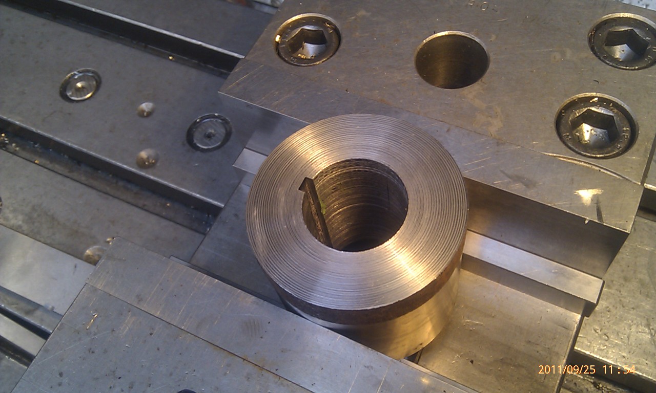
This picture maybe help you all understand what I'm about to try out.
This is an 20B-front just for show.
I will now make an fixture to hold the same of mine, the with the spindle off, cut about 0.1mm at time i stages untill i got the right keyway.
This is an 20B-front just for show.
I will now make an fixture to hold the same of mine, the with the spindle off, cut about 0.1mm at time i stages untill i got the right keyway.
 09-25-2011, 05:30 AM
#94
Senior Member
Thread Starter
Join Date: Sep 2003
Posts: 229
09-29-2011, 12:13 PM
#96
Junior Member

Join Date: Jun 2011
Location: Pennsylvania
Posts: 8
Tegheim.. are you using CAM software to import your 3D models into programming language for the machining centers or are you writing the G-code for all the CNC work? I figure you are just following factory spec. for this project, have you thought about making any modifications eventually.. having the models and given the analysis packages available for solidworks you could play with material, weight, etc.
10-01-2011, 03:54 AM
#97
Senior Member
Thread Starter
Join Date: Sep 2003
Posts: 229
Time for a little update!
Sadly my HTC Desire isn't the best camera in workshop-lights...
Have finally got along with the Keyway!
First, I did new irons to the vise (correct name? Google translate)
They are mounted from the inside with M10-bolts
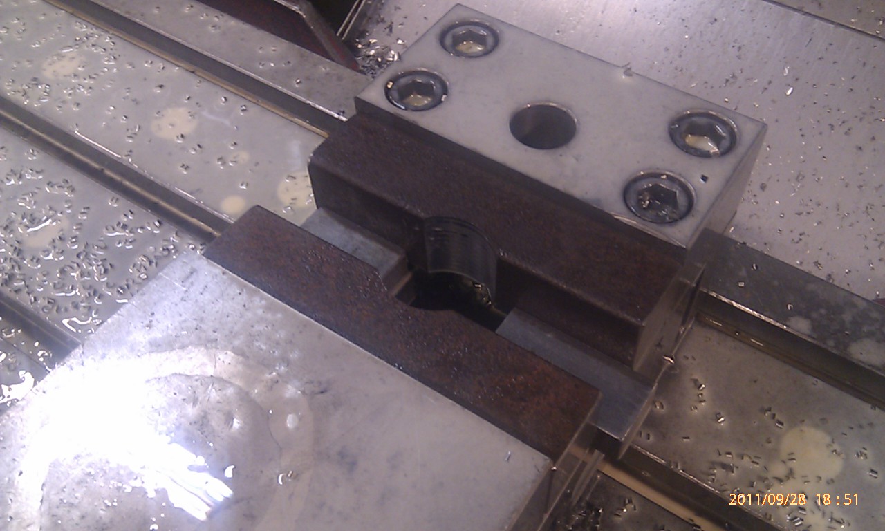
A hole at 43.61mm, and an Radius 6.0mm to give clearance for Radius 5.0mm on the eccentric.
This is not bored, so the surface is just roughed yet.
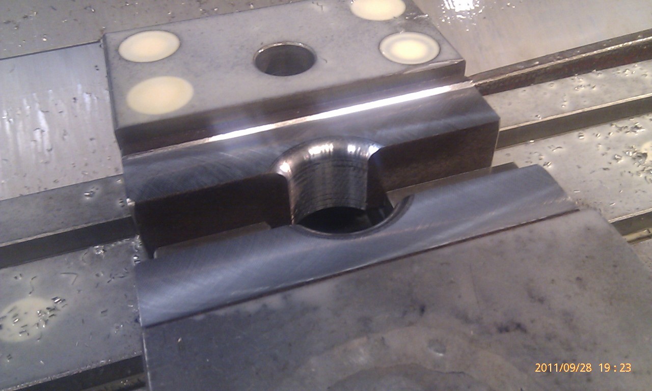
Exact precision!
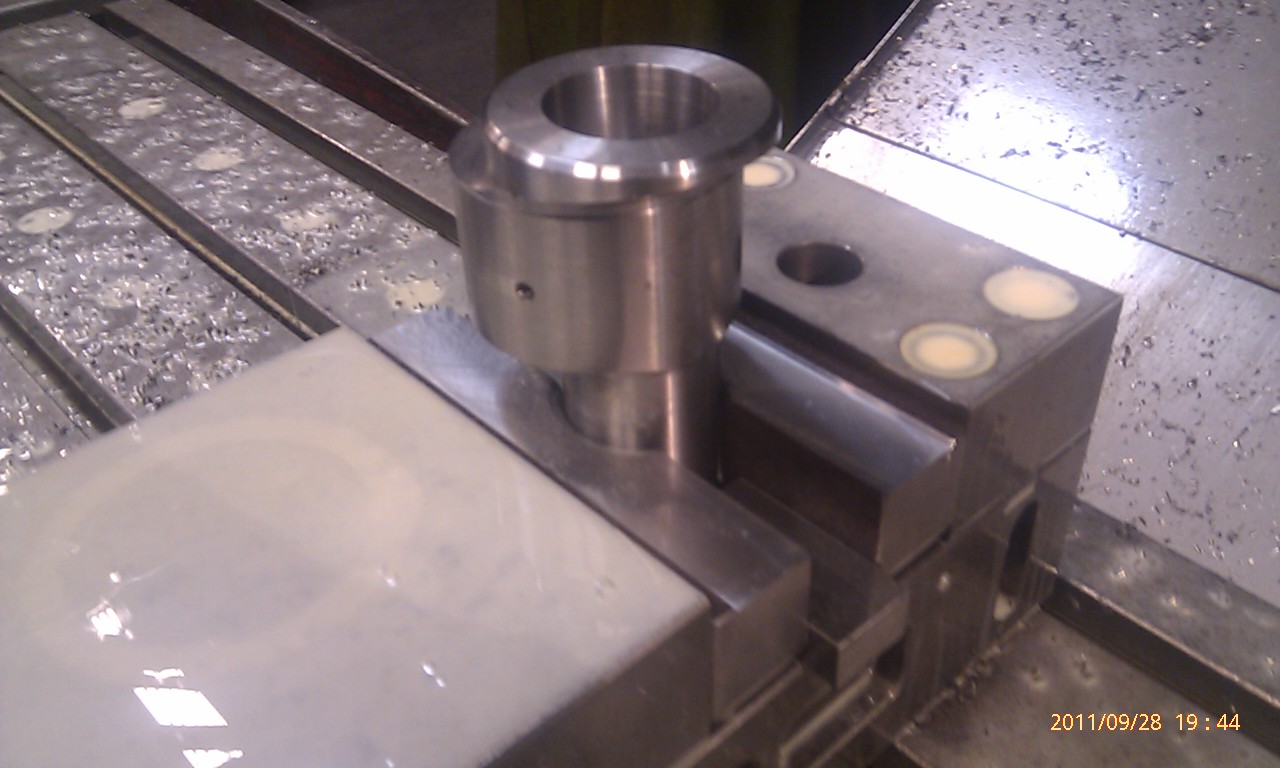
Like a glove!

Indication of a cam, I have my zero point where I did the fixture, so then you have easy track of the eccentric theory should lie on the X 15.0mm Y0.0mm.
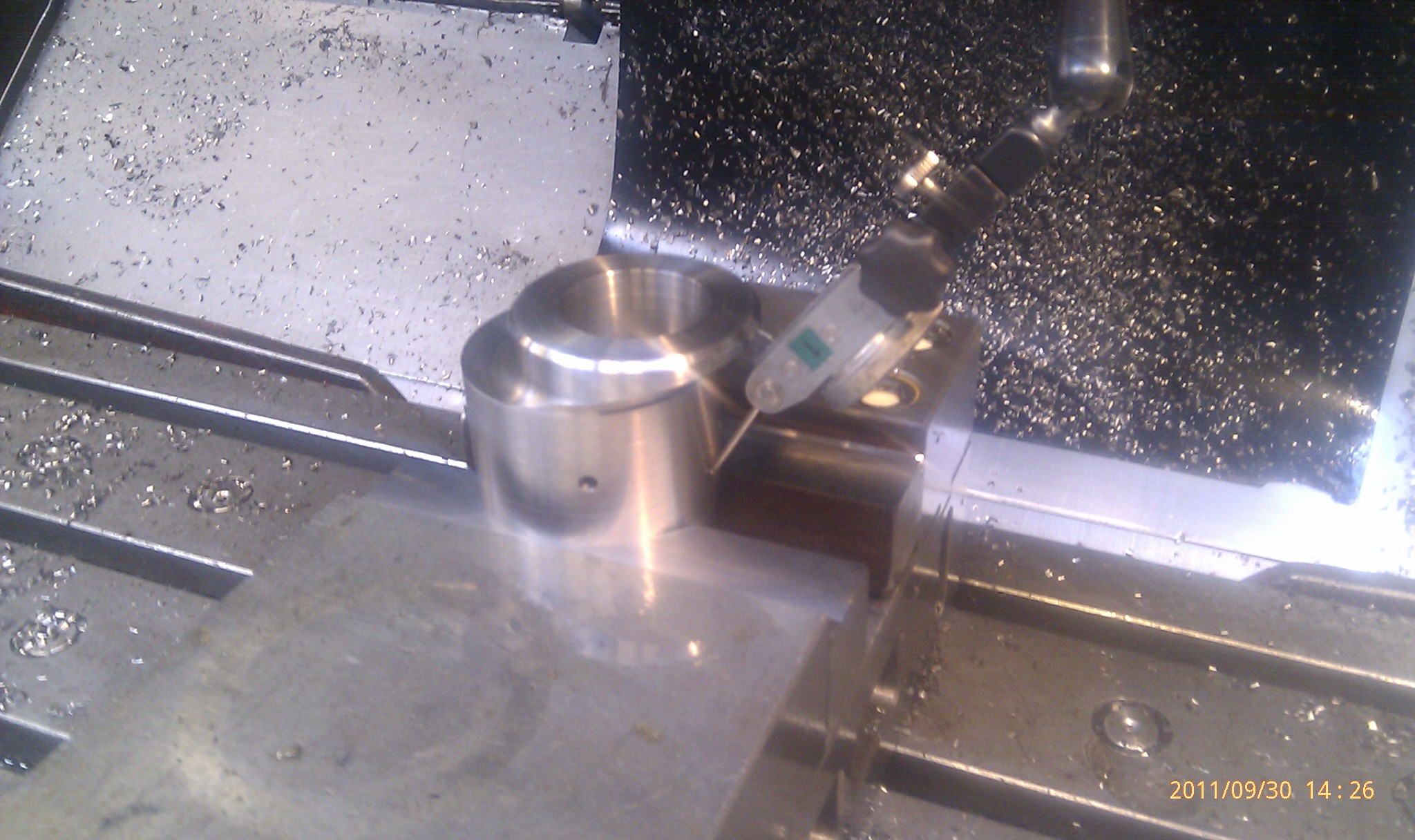
A final inspection of the tool. Indicates the track of the tool in the X-axis, thus I know that it is angled precisely 90grd.
Using the M-code M19 in the machine, so I lock the spindle in the same place every time.
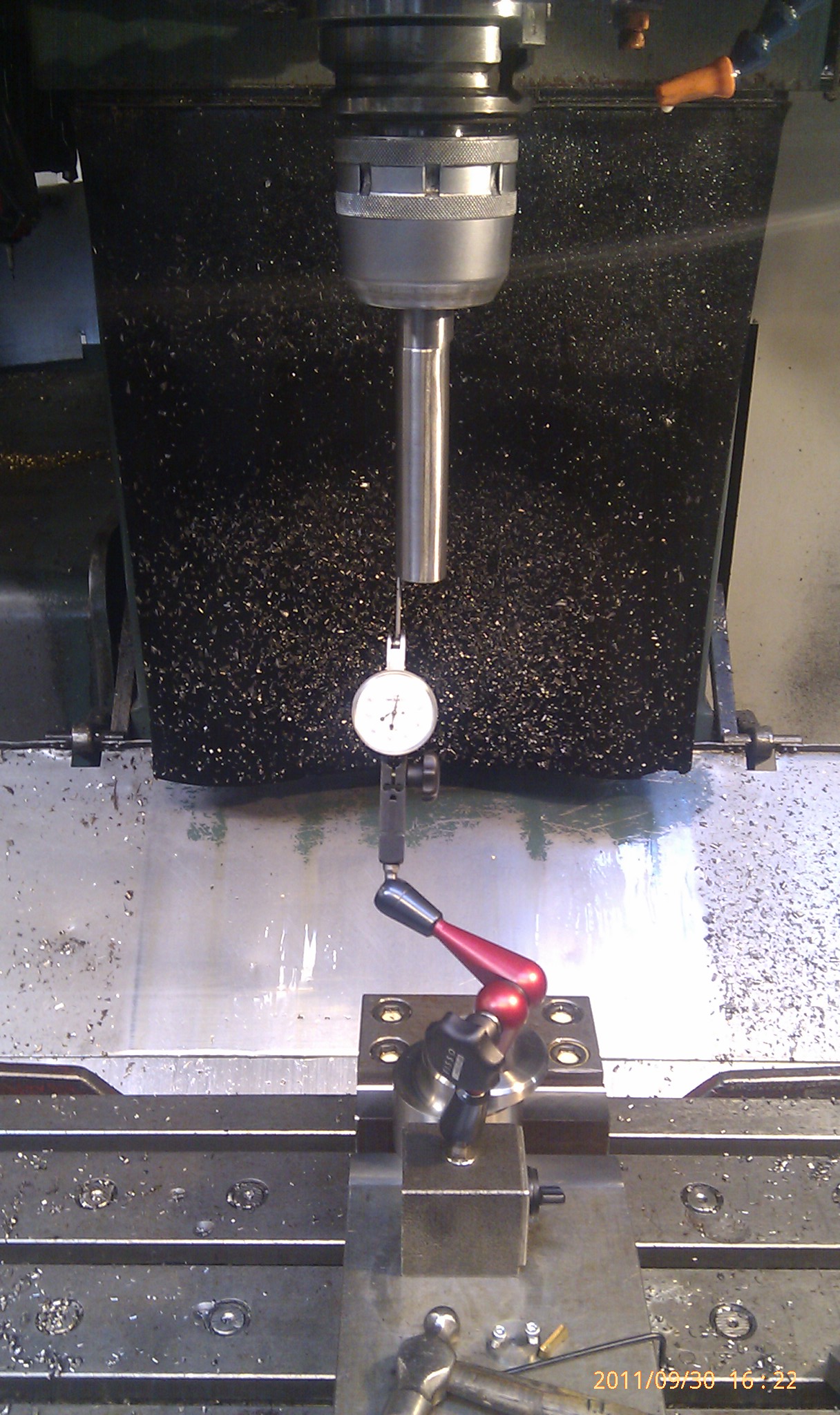
This is what working out, it will actually go much faster, when the cutting speed in such a cut is about 80-120m/min, ie as soon as it will go through the material. Easy as it spins to get the cutting speed, but now the cut stands still. So I drive 2m/min or F2000.0 as many may know. Takes just 0.1mm per insert to avoid accidents in my fine pieces
[media]http://www.youtube.com/watch?v=wqGoEAxAFRQ[/media]
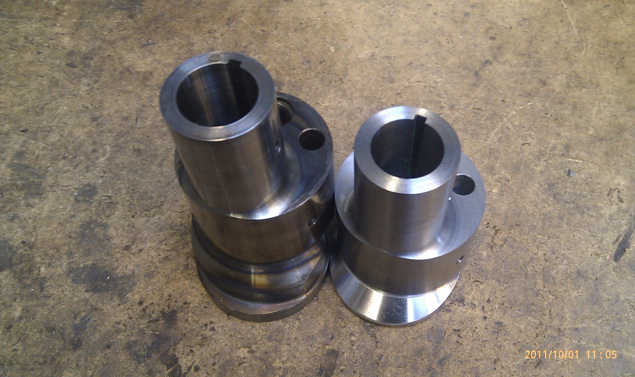
Results! Keyway on 5.00-5.01mm width, and depth with little clearance.

Sadly my HTC Desire isn't the best camera in workshop-lights...
Have finally got along with the Keyway!
First, I did new irons to the vise (correct name? Google translate)
They are mounted from the inside with M10-bolts
A hole at 43.61mm, and an Radius 6.0mm to give clearance for Radius 5.0mm on the eccentric.
This is not bored, so the surface is just roughed yet.
Exact precision!
Like a glove!
Indication of a cam, I have my zero point where I did the fixture, so then you have easy track of the eccentric theory should lie on the X 15.0mm Y0.0mm.
A final inspection of the tool. Indicates the track of the tool in the X-axis, thus I know that it is angled precisely 90grd.
Using the M-code M19 in the machine, so I lock the spindle in the same place every time.
This is what working out, it will actually go much faster, when the cutting speed in such a cut is about 80-120m/min, ie as soon as it will go through the material. Easy as it spins to get the cutting speed, but now the cut stands still. So I drive 2m/min
or F2000.0 as many may know. Takes just 0.1mm per insert to avoid accidents in my fine pieces [media]http://www.youtube.com/watch?v=wqGoEAxAFRQ[/media]
Results! Keyway on 5.00-5.01mm width, and depth with little clearance.
10-02-2011, 11:26 AM
#98
Member

Join Date: Oct 2010
Location: Netherlands
Posts: 34
Looks good!
I wish I had that sort of equipment at my disposal, I'm attempting something similar with conventional machines, lots and lots of work.
What sort of heat treatment did the shaft get? Looking at the pictures it looks like the shaft was hardened and annealed.
How much room did you leave for grinding, about 0,5mm's?