Oil System Mods
 12-21-2007, 08:30 AM
#1
Member
Thread Starter

Join Date: Dec 2007
Location: EastCoast , Florida
Posts: 78
Hello Ppl , I have been trying on searching for the oil mods to the front and rear plates for the stationary's and can not fing anything on it but a pic of the port timing topic , I need everyones help on this so I can go this route on my all out racing motor Instructions and pics would be very helpfull . Thanks to everyone who is willing to contribute to this topic !
 (40.47K) Thanks , Gilbert
(40.47K) Thanks , Gilbert
 12-22-2007, 09:36 AM
#2
Fabricator


Join Date: Jan 2004
Location: Central Ohio (Hebron) Zephyrhills Fla.
Posts: 1,322
Originally Posted by 13BT_Starlet' post='890550' date='Dec 21 2007, 07:30 AM
Hello Ppl , I have been trying on searching for the oil mods to the front and rear plates for the stationary's and can not fing anything on it but a pic of the port timing topic , I need everyones help on this so I can go this route on my all out racing motor Instructions and pics would be very helpfull . Thanks to everyone who is willing to contribute to this topic !
(40.47K) Thanks , Gilbert
(40.47K) Thanks , GilbertSince you were nice enough to publish one of my photos, how can I refuse?
In the picture there is a dash 12 line from the oil filters into the inner oil gallery that runs down to the rear main bearing and supplies the dowel gallery running to the front vertical gallery that feeds the front main bearing. You didn't say what kind of racing you want to do, so I am describing a road racing system.
There is usually not enough oil feeding the front main bearing, so we drill out the brass plug in the front latteral gallery intersecting the vertical gallery oil flow from the dowel gallery. That hole is opened up in a verticle mill and the hole is faced off and threaded for a hydraulic boss fitting in dash 10. Unseen in the photo is an additional dash 10 fitting below the dash 12, that feeds a dash 10 line to this new front oil fitting.
The idea here is to more than double the cross section of the oil supply to the front main bearing.
OK. Here we can go two ways: dry sump with a flat plate on the engine instead of an oil pan, or wet sump with the original or an aftermarket oil pan.
For the dry sump, oil pressure is controlled at the pump and no relief valve is used at all on the rear iron. The banjo fitting where the stock oil line enters the rear iron is just a plug to keep dirt out. The outer vertical gallery is not used for anything. The only oil line feeding the engine is the one you see in the picture.
For a wet sumped engine, you would do the mods in the front iron below the oil pump, as in rounding the entry into the drilled galleries to eliminate sharp corners for oil exiting the pump and for the oil from the pickup gallery entering the plenum below the pump. Use a small ball pit in a die grinder. Use many layers of racers (duct) tape on the pump mounting serface to keep from ruining the iron.
If you have a junk front iron, practice on that.
For the wet sump I would bypass the stock junction into the front cover. Mazda has been screwing with that weak point since day one. The front cover is not very stiff and when you jack up the oil pressure and rev the engine the front cover is pushed out and the "O" ring at this junction is released.
Followed by no oil pressure, and seconds later, by no engine. So I would cut a sheet metal disc to fit that hole, lay the "O" ring on top of that when assembling. The latteral gallery would get the same dash 10 fitting as the adjacent gallery from the filter adaptor. So oil pressure out of the engine is from the side of the front iron instead of the flexible front cover. The outlet in the cover gets a plug.
Replace the stock pressure relief valve in the rear iron with a Racing Beat 115 PSI unit.
If you plan to use the stock OMP rather than premix, then that disc needs to have a .020" hole in the center. The crank metering jets are fine stock until you get above 9,000 RPM. Removing the bug screen from the pickup is a help. Adding a radius to the end of the pickup tube is a big help. Safety wire the pickup tube bolts.
Use a K&N filter on a remote mount, or a NAPA filter on the stock mount. Use Redline 40 Wt. Racing oil in the sump, and premix one oz per gallon of Redline 2 cycle oil. Water temps not over 180, oil not over 190. Timing to 25 to 27 both, no split.
Read all of the tech articles on Paul Yaws web page. www.yawpower.com
Buy and read all of the Racing Beat tech/catalog.
Find the schematic for the oil system and learn it byheart.
Never pretend that Fram makes oil filters. Fram makes crap, not oil filters.
Lynn E. Hanover
12-22-2007, 01:44 PM
#3
Member
Thread Starter
Join Date: Dec 2007
Location: EastCoast , Florida
Posts: 78
Hello Lynn , Thanks for replying . I appologize for not describing the engine , it is going to be for drag racing only with the wet sump stock 1st gen oilpan . We will be premixing the fuel , my question is as for the chain lubrication if the front oil port on the front cover is block off what would lubricate the chain ? Do you have any pics on your set up or any others ? I dont think it would be any diffrence from road racing to drag racing other than the turns as you describe everything for road racing in general , correct me if I'm wrong learnig new things every day .
Merry Christmas and a prosperous New Year to you and Everyone on this forum
Gilbert
Merry Christmas and a prosperous New Year to you and Everyone on this forum
Gilbert
12-22-2007, 06:12 PM
#4
Fabricator
Join Date: Jan 2004
Location: Central Ohio (Hebron) Zephyrhills Fla.
Posts: 1,322
Originally Posted by 13BT_Starlet' post='890601' date='Dec 22 2007, 12:44 PM
Hello Lynn , Thanks for replying . I appologize for not describing the engine , it is going to be for drag racing only with the wet sump stock 1st gen oilpan . We will be premixing the fuel , my question is as for the chain lubrication if the front oil port on the front cover is block off what would lubricate the chain ? Do you have any pics on your set up or any others ? I dont think it would be any diffrence from road racing to drag racing other than the turns as you describe everything for road racing in general , correct me if I'm wrong learnig new things every day .
Merry Christmas and a prosperous New Year to you and Everyone on this forum
Gilbert
Merry Christmas and a prosperous New Year to you and Everyone on this forum
Gilbert
OK.
Do the pickup mod with the screen off. Bore out the center of a thick washer to fit tight right on the end of the pickup tube. Braze the washer in place with a generous fillet. Use the die grinder to radius the tube to washer junction, so it looks like a little trumpet bell.
Make up a baffle of any metallic sheetstock that has only one drain back hole. about 3" diameter right around the pickup. The idea here is that when you launch, all of the oil will exit the sump and pile up at the very rear of the pan. There is a lot of open volume back there and most of the oil supply will fit in there just fine. So most of the pass ends up with little oil pressure. Bad mojo.
In road racing that drainback hole is centered under the center iron drainback because under braking from about 140 MPH and 9,600 RPM the entire oil supply will fill up the front case and uncover the pickup. So the baffle is a must for hard racing. If you cannot hold your top oil pressue all the way to the end, make the deep part of the pan deeper and extend the pickup.
The pump chain is oiled by a oil metering hole in the top of the pump where the set screw is located that keeps the center element in the pump indexed.
I will add some data to a picture of a front iron and post that.
The dry sump system is completely different. The engine has a flat plate on the bottom instead of a pan. Oil is stored in a tall round oil tank. A very large diameter hose from the tank bottom to the inlet side of the pressure section of a 3 stage oil pump. The pressureised oil is pumped through a pair of K&N filter elements then one 13 row cooler, then into that dash 12 line in the picture.
Used oil falls onto the flat plate and is sucked up by 2 pickup tubes that lead to bulkhead fittings in the front cover. Then through dash 10 lines to the suction side of the 2 scavenge sections of the pump and then through 2 inline Peterson screen filters then into 2 more 13 row coolers then into the storage tank. The only way to uncover the pickup is to turn the car upside down. Also bad mojo.
I will modify a picture and post it.
Lynn E. Hanover
12-22-2007, 07:58 PM
#5
Fabricator
Join Date: Jan 2004
Location: Central Ohio (Hebron) Zephyrhills Fla.
Posts: 1,322
Originally Posted by Lynn E. Hanover' post='890611' date='Dec 22 2007, 05:12 PM
OK.
Do the pickup mod with the screen off. Bore out the center of a thick washer to fit tight right on the end of the pickup tube. Braze the washer in place with a generous fillet. Use the die grinder to radius the tube to washer junction, so it looks like a little trumpet bell.
Make up a baffle of any metallic sheetstock that has only one drain back hole. about 3" diameter right around the pickup. The idea here is that when you launch, all of the oil will exit the sump and pile up at the very rear of the pan. There is a lot of open volume back there and most of the oil supply will fit in there just fine. So most of the pass ends up with little oil pressure. Bad mojo.
In road racing that drainback hole is centered under the center iron drainback because under braking from about 140 MPH and 9,600 RPM the entire oil supply will fill up the front case and uncover the pickup. So the baffle is a must for hard racing. If you cannot hold your top oil pressue all the way to the end, make the deep part of the pan deeper and extend the pickup.
The pump chain is oiled by a oil metering hole in the top of the pump where the set screw is located that keeps the center element in the pump indexed.
I will add some data to a picture of a front iron and post that.
The dry sump system is completely different. The engine has a flat plate on the bottom instead of a pan. Oil is stored in a tall round oil tank. A very large diameter hose from the tank bottom to the inlet side of the pressure section of a 3 stage oil pump. The pressureised oil is pumped through a pair of K&N filter elements then one 13 row cooler, then into that dash 12 line in the picture.
Used oil falls onto the flat plate and is sucked up by 2 pickup tubes that lead to bulkhead fittings in the front cover. Then through dash 10 lines to the suction side of the 2 scavenge sections of the pump and then through 2 inline Peterson screen filters then into 2 more 13 row coolers then into the storage tank. The only way to uncover the pickup is to turn the car upside down. Also bad mojo.
I will modify a picture and post it.
Lynn E. Hanover
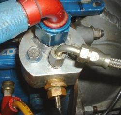
I have no pictures of the fitting side of a front iron. This is as close as I have. You would have two "O" ring boss fittings installed here. The upper fitting is for the oil line from the filter adaptor. The lower fitting is in the gallery from the pump. The opening into the front cover is blocked. Oil out goes to the remote filter mount (flow is outside to inside) and then to the cooler, then into the banjo fitting at the bottom of the rear iron. Do not use pipe fittings in the front iron. The tapered fitting will crack the iron and ruin it. Trust me on this...........
Lynn E. Hanover
12-22-2007, 08:38 PM
#7
Member
Thread Starter
Join Date: Dec 2007
Location: EastCoast , Florida
Posts: 78
I have no pictures of the fitting side of a front iron. This is as close as I have. You would have two "O" ring boss fittings installed here. The upper fitting is for the oil line from the filter adaptor. The lower fitting is in the gallery from the pump. The opening into the front cover is blocked. Oil out goes to the remote filter mount (flow is outside to inside) and then to the cooler, then into the banjo fitting at the bottom of the rear iron. Do not use pipe fittings in the front iron. The tapered fitting will crack the iron and ruin it. Trust me on this...........
Lynn E. Hanover
Attached thumbnail(s)
Reduced 74%
960 x 720 (98.27K)
Sorry Lynn I was posting while you posted the pic . Now a big question in mind by doing this mod the pressure release valve on the front cover will it function or does it needs to be removed since the front cover is being blocked off ?
ok let me see if I got this right , from the front steel the lower fitting gallery from pump to the remote oil filter to the oil filter adapter or to the oil cooler ? then adapter to the top fitting on the front steel which is the gallery for the stationary and from the rear steel banjo back to the cooler . I am confused with the oil lines configuration , correct me on what I have wrong , Thanks
Gilbert
12-23-2007, 06:45 PM
#8
Fabricator
Join Date: Jan 2004
Location: Central Ohio (Hebron) Zephyrhills Fla.
Posts: 1,322
Originally Posted by 13BT_Starlet' post='890623' date='Dec 22 2007, 07:38 PM
I have no pictures of the fitting side of a front iron. This is as close as I have. You would have two "O" ring boss fittings installed here. The upper fitting is for the oil line from the filter adaptor. The lower fitting is in the gallery from the pump. The opening into the front cover is blocked. Oil out goes to the remote filter mount (flow is outside to inside) and then to the cooler, then into the banjo fitting at the bottom of the rear iron. Do not use pipe fittings in the front iron. The tapered fitting will crack the iron and ruin it. Trust me on this...........
Lynn E. Hanover
Attached thumbnail(s)
Reduced 74%
960 x 720 (98.27K)
Sorry Lynn I was posting while you posted the pic . Now a big question in mind by doing this mod the pressure release valve on the front cover will it function or does it needs to be removed since the front cover is being blocked off ?
ok let me see if I got this right , from the front steel the lower fitting gallery from pump to the remote oil filter to the oil filter adapter or to the oil cooler ? then adapter to the top fitting on the front steel which is the gallery for the stationary and from the rear steel banjo back to the cooler . I am confused with the oil lines configuration , correct me on what I have wrong , Thanks
Gilbert
Lynn E. Hanover
Attached thumbnail(s)
Reduced 74%
960 x 720 (98.27K)
Sorry Lynn I was posting while you posted the pic . Now a big question in mind by doing this mod the pressure release valve on the front cover will it function or does it needs to be removed since the front cover is being blocked off ?
ok let me see if I got this right , from the front steel the lower fitting gallery from pump to the remote oil filter to the oil filter adapter or to the oil cooler ? then adapter to the top fitting on the front steel which is the gallery for the stationary and from the rear steel banjo back to the cooler . I am confused with the oil lines configuration , correct me on what I have wrong , Thanks
Gilbert
OK,
The oil leaves the front iron through the new lower boss fitting into a dash 10 hose that runs to the outside hole of a remote filter stand.
From the center hole of the filter stand into a dash 10 hose to the lower fitting on your oil cooler.
From the upper fitting on your oil cooler into a dash 10 hose to your aluminum block that replaces your stock filter adapter. The inner and outer holes of the block will be connected inside the block. This is required for the rear pressure relief to work. The banjo fitting hole at the bottom of the iron must be plugged. The stock oil pressure sender hole may be used, or provision made in the block.
The oil into the engine could also be through the stock banjo fitting but requires several more 90 degree turns inside the engine, that are eliminated by using the block. In both cases the inner and outer holes must be connected inside the block.
A 1/2� Pipe by AN10 fitting is installed into the block to provide oiling to the front main bearing.
So from the block in a dash 10 hose to the new upper boss fitting in the front iron and that completes the oiling system.
Pack the pump with wheel bearing grease on assembly.
Remove the oil in line from the block and allow it to hang into a coffee can. Remove the plugs and disable the ignition system. Spin the engine with the starter until a solid stream of oil is running into the can.
Reconnect the hose to the block. Spin the engine until you see oil pressure.
Fill oil level to 1/4� above the baffle. I just kept shortening the dip stick until it would not touch the baffle. So 1/4� from the end of the stick was full oil.
If you are not using the OMP, just pop off the snap ring and remove the gear. You can change your mind later with little fuss.
Aircraft fittings and hoses are measured in 1/16�. So a dash 16 hose or fitting has a one inch inside
diameter. A dash 4 hose is 1/4� ID and so on. AN is Air force/Navy standard. It is often stamped on the fittings. As well as the size. Similar looking industrial fittings and hoses will fit AN hose and fittings.
However, the Industrial flare angle is 37 � degrees. AN is 45 degrees. They will seal against each other, but you may split a flair if you over tighten one.
Lynn E. Hanover
12-23-2007, 09:03 PM
#9
Fabricator
Join Date: Jan 2004
Location: Central Ohio (Hebron) Zephyrhills Fla.
Posts: 1,322
Sorry Lynn I was posting while you posted the pic . Now a big question in mind by doing this mod the pressure release valve on the front cover will it function or does it needs to be removed since the front cover is being blocked off ?
Gilbert
[/quote]
If you want to run the OMP by drilling a .020" hole in the blocking disc, you need to leave the relief valve in place. It will never cycle, just fill up the hole.
Lynn E. Hanover
Gilbert
[/quote]
If you want to run the OMP by drilling a .020" hole in the blocking disc, you need to leave the relief valve in place. It will never cycle, just fill up the hole.
Lynn E. Hanover