
In Chamber Pressure Testing


Thread Starter
Member
Joined: Jun 2004
Posts: 52
From: Slidell, LA
If you have not seem this on the other forums I didn't want you to miss this.
I have been working with pressure sensors to try and understand what is going on inside the rotor chamber.
What I am finding is that the best peak pressures seem to be located around 45� ATDC.
But notice the variation of cycles. We think of a more even flow of power pulses.
This log is taken while accelerating through 5000 rpm. The range above this is still too retarded.
Thread Starter
Member
Joined: Jun 2004
Posts: 52
From: Slidell, LA
The test equipment is made by TFX Engine Technology.
You can familiarize yourself with the program by going to http://www.tfxengine.com/hardware3.html
The test mule is a RE 13b running 12 psi (10 psi spring)
TO4s, HKS cast divided
50/50 meth water pre and post turbo.
HKS Twinpower
Power FC
You can familiarize yourself with the program by going to http://www.tfxengine.com/hardware3.html
The test mule is a RE 13b running 12 psi (10 psi spring)
TO4s, HKS cast divided
50/50 meth water pre and post turbo.
HKS Twinpower
Power FC
Thread Starter
Member
Joined: Jun 2004
Posts: 52
From: Slidell, LA
More interpretation.
The red arrows indicate an engine misfire (in this case the mixture was too rich) .
The blue arrows depict a too retarded cycle at about 60� with subsequent lower pressure.
The green arrow show a cycle closer to 45� and higher pressure.
I am amazed at the scatter.

The red arrows indicate an engine misfire (in this case the mixture was too rich) .
The blue arrows depict a too retarded cycle at about 60� with subsequent lower pressure.
The green arrow show a cycle closer to 45� and higher pressure.
I am amazed at the scatter.

Thread Starter
Member
Joined: Jun 2004
Posts: 52
From: Slidell, LA

This is what the burn rate looks like. (One of the best examples of the 210 samples taken during this log.)
The red line is the pressure of rotor compression without ignition.
The blue line is ignited pressure.
The purple line is the temperature of the burning mixture. Notice it is still 1400�C when the exhaust port opens.
The pressure at exhaust port opening (EOP) is 91 psi.
A detonation rating of 65/88/0 shows up for this #64 cycle. Since it has 0 frequency I am assured by the Mentor that it is benign. (But whenever the peak pressure is advanced below 45� it gets some of these readings.)
The HP and torque readings are off in this sample because I am using the wrong displacement calculations.
Thread Starter
Member
Joined: Jun 2004
Posts: 52
From: Slidell, LA
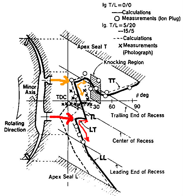
There are a lot of concepts to interrelate when considering what is going on inside of a rotary engine.
This is from a Mazda paper Rotary86v6a4, Fig. 14, showing flame propagation.
I think this is probably Mazda Research at its best!
If you haven't seen it before please take your time trying to understand it.
Some things to note:
Because the mixture is flowing the flame front hardly moves upstream at all. In fact the trailing portions of both flame patches are pushed backwards part of the time.
The squish generation and trench shape further complicates this movement.
When the leading and trailing flame fronts collide (at about 20� ATDC) that their speed diminishes.
The knock region is from 30� - 45� ATDC and where the knock sensor is located.
Thread Starter
Member
Joined: Jun 2004
Posts: 52
From: Slidell, LA
Good news and bad news.
As the mean effective pressure has increased through changes in timing a new problem has arisen. Preignition!
The in-chamber testing can show us the beginning of combustion pressure from the small ignited kernel of flame front, but it is so small at first that the pressure change usually only shows an increase after about 5� of eccentric movement (15� BTDC advance starts showing pressure at 10� BTDC). Imagine our surprise when we started seeing a pressure rise starting at 28� BTDC!
The crazy thing is that it made more power and no real detonation!
Barry


Junior Member
Joined: Jan 2009
Posts: 7
Are you only measuring pressure from one plug? Plan on using both leading and trailing sensors to see spread times etc?
I would very much like to see testing at the same conditions down to zero split with less advanced timing to see what gives the best net BMEP considering the negative pumping losses on compression and pressure rise time from point of ignition, given mazdas race engine had various multi plug combos I have a feeling for outright power from a given charge that in most conditions a zero split (providing combustion is controlled) should give peak torque/power.
Do you mind stating which model TFX logger you have and what plugs/other sensors you are running. I am assuming they have set up the total power/torque calcs for the rotary on a theoretical base from the geometry (with fudged factors for the pressures in the exhaust stroke, unless you are running sensors near/in the exhaust port or manifold) given the sensors cannot see to the end of the power stroke let alone beyond it. I might look to purchase my own in the future.