
4 Rotor Build


Thread Starter
Member
Joined: Oct 2010
Posts: 34
From: Netherlands
I thought I should post up some pictures of the 4 rotor engine I'm building.
I've been researching, figuring stuff out and doing a lot of CAD work on it for about a half year, but I've only begun to build it about a month ago or so.
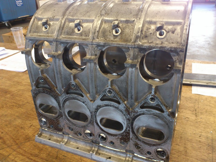
So far I've modified a few 13B n/a rotor housings, and I've been busy with the new eccentric shaft.
When done this should be a peripheral ported n/a 4rotor.
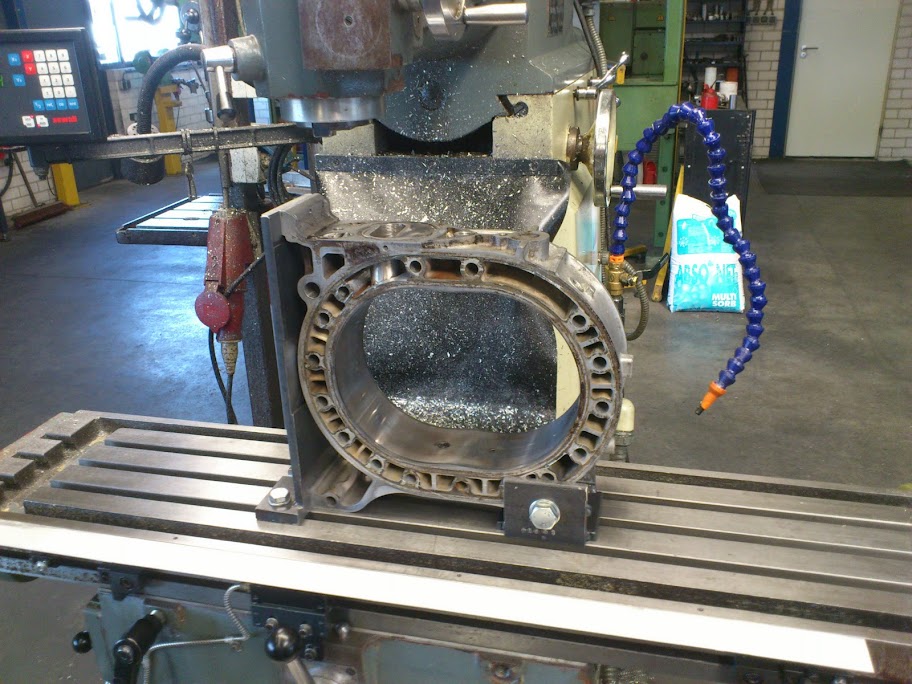
I started by modifying some rotor housings.
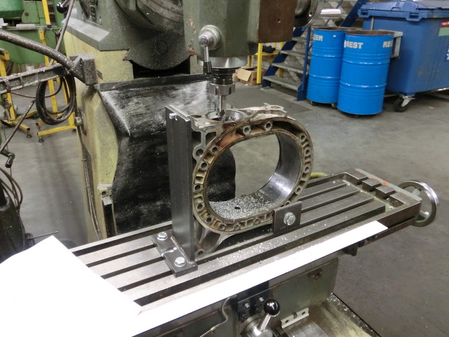
I made a jig to position the housings in my milling machine and ported the exhausts:
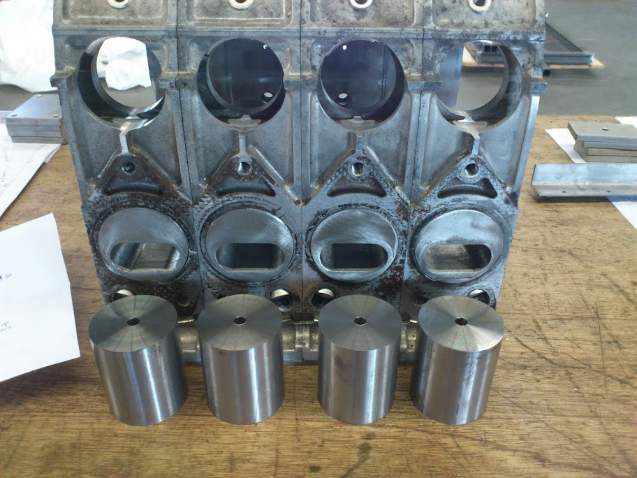
Next job was making some thickwalled stainless steel exhaust inserts.
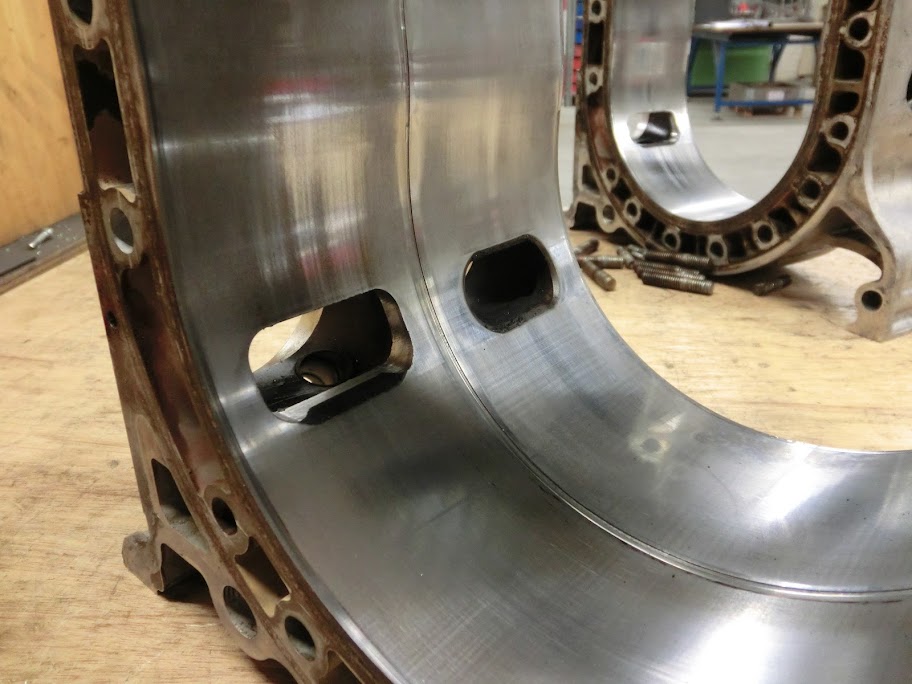
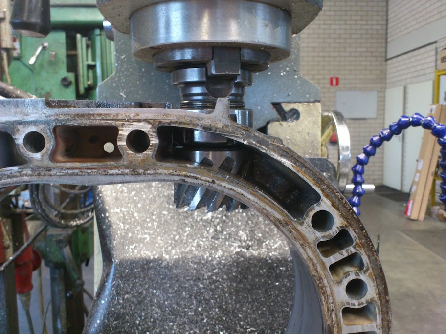
The exhaust channels had to be milled out to accomodate for the inserts. The inserts are way larger than stock, because they have a more rectangular shape, are wider, and they are thicktubed so they will last under harsh conditions. Therefore there was a lot of milling to do. I found that after milling the exhaust channel would become dangerously thin, and could possibly crack, so I went a bit out of the box, and inserted entirely new channels to my likings. Kind of like when you add a peripheral port. This allowed me to get the port timings and shapes exactly the way I wanted them. I haven't made a lot of pictures from the new channels but you can see them in the following pictures.
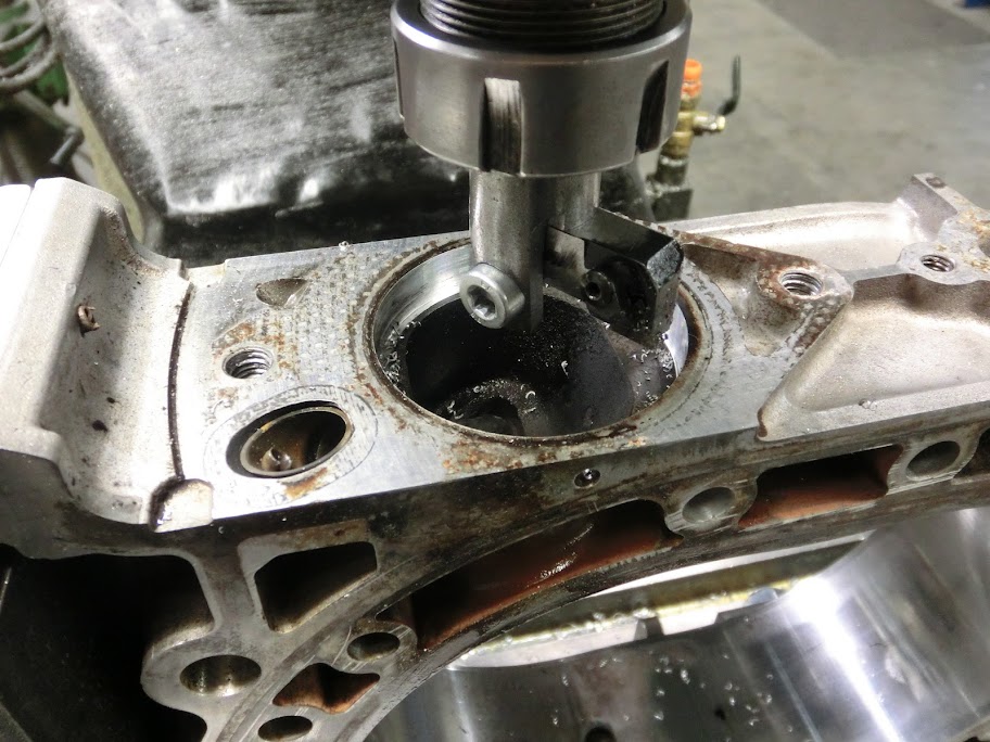
Here the housings were getting peripheral ports, first job was making some holes.
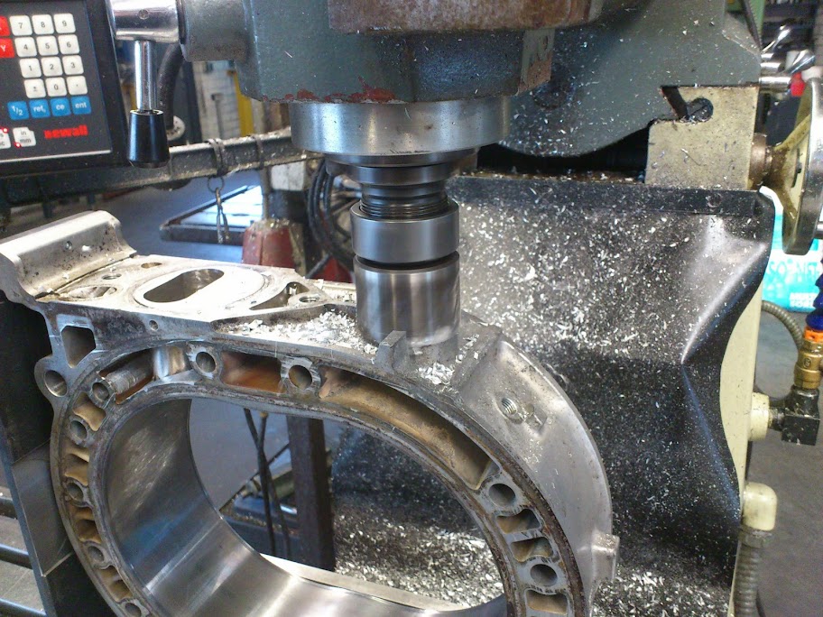
After the hole was milled I finished the hole with a boring bar.
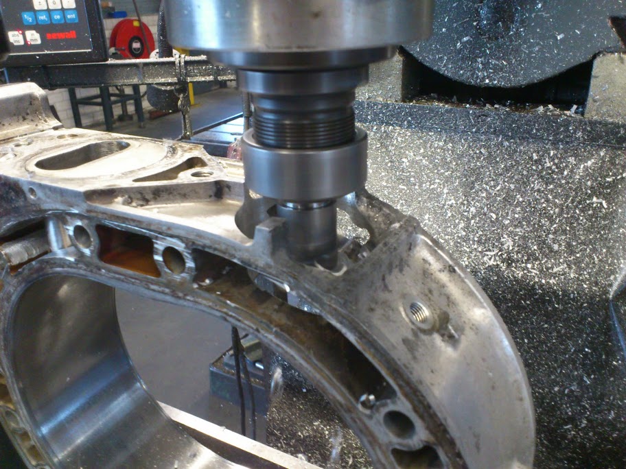
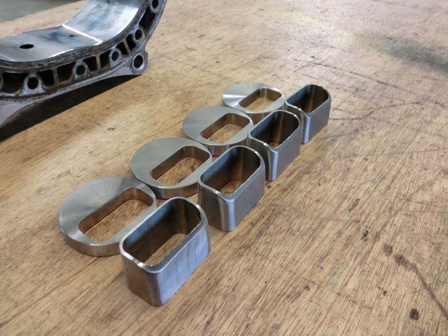
I'm using stainless steel inserts made out of 304 roundbar
I've been researching, figuring stuff out and doing a lot of CAD work on it for about a half year, but I've only begun to build it about a month ago or so.
So far I've modified a few 13B n/a rotor housings, and I've been busy with the new eccentric shaft.
When done this should be a peripheral ported n/a 4rotor.
I started by modifying some rotor housings.
I made a jig to position the housings in my milling machine and ported the exhausts:
Next job was making some thickwalled stainless steel exhaust inserts.
The exhaust channels had to be milled out to accomodate for the inserts. The inserts are way larger than stock, because they have a more rectangular shape, are wider, and they are thicktubed so they will last under harsh conditions. Therefore there was a lot of milling to do. I found that after milling the exhaust channel would become dangerously thin, and could possibly crack, so I went a bit out of the box, and inserted entirely new channels to my likings. Kind of like when you add a peripheral port. This allowed me to get the port timings and shapes exactly the way I wanted them. I haven't made a lot of pictures from the new channels but you can see them in the following pictures.
Here the housings were getting peripheral ports, first job was making some holes.
After the hole was milled I finished the hole with a boring bar.
I'm using stainless steel inserts made out of 304 roundbar
Thread Starter
Member
Joined: Oct 2010
Posts: 34
From: Netherlands
Finished inserts, I figured I might as well add injector bungs and a groove for an o-ring here since I'm planning on making a slide throttlebody that sits directly onto the housings.
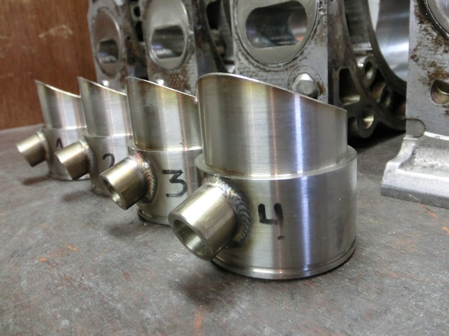
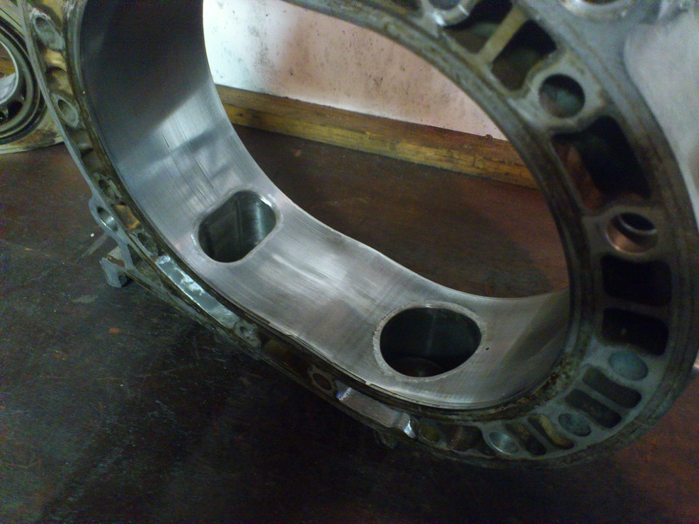
Here are the housings just before pressing in the inserts, they are a light pressfit. The waterchannel was "ported", the defcon will bond better this way.
With inserted inserts. I've put some devcon on the inserts before inserting, you can see some of it on the outside, this will help sealing.
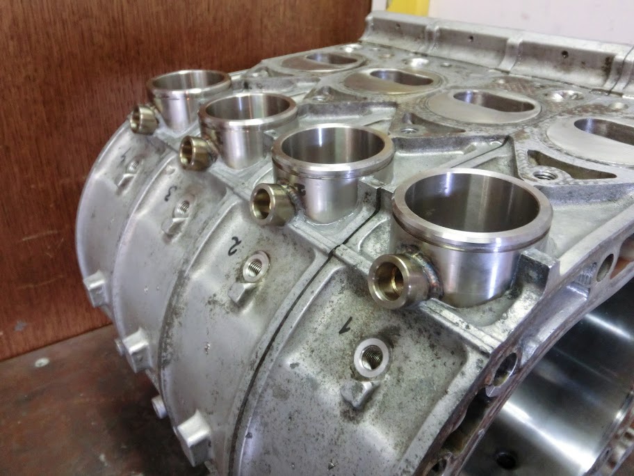
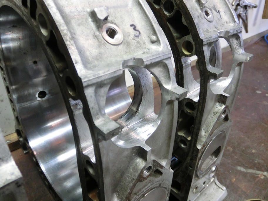
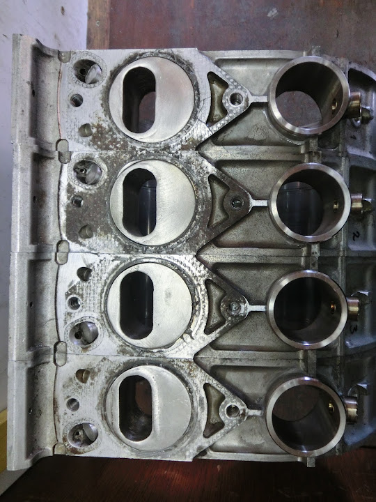
Inlets, Outlets, plain and simple, I still need to fill up those air-emission hole things, mill the exhaust flange surface flat, and clean everything up.
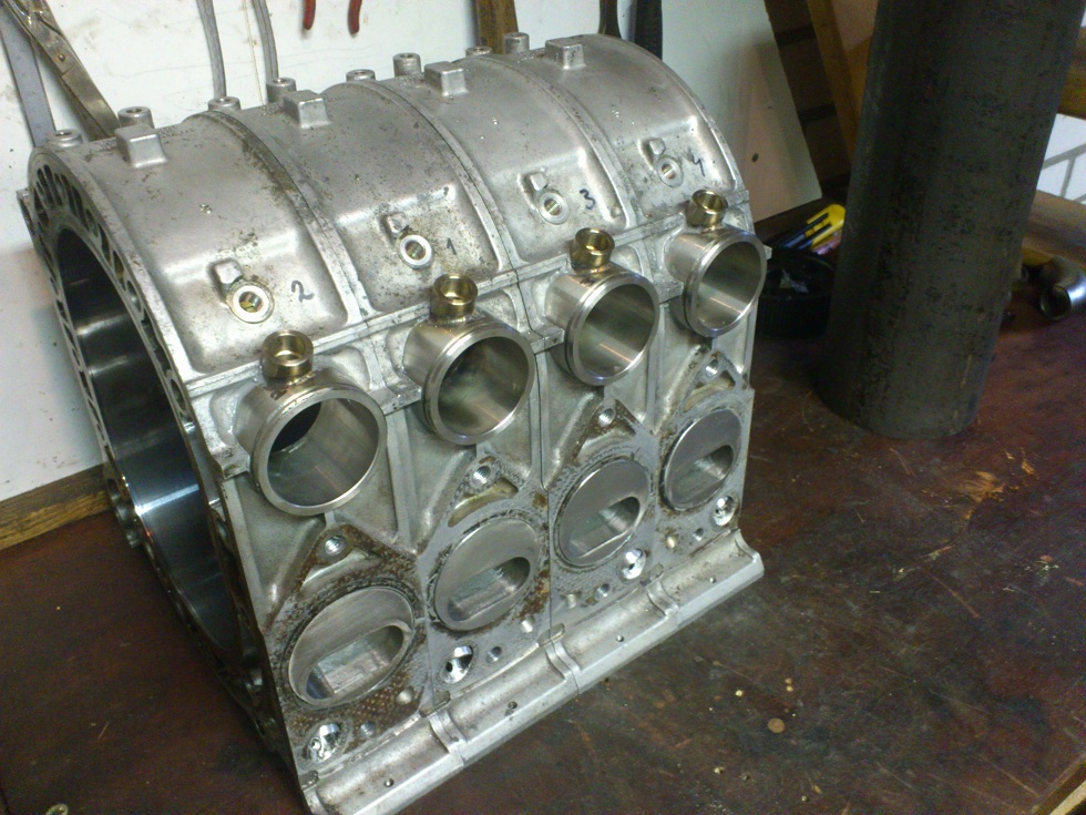
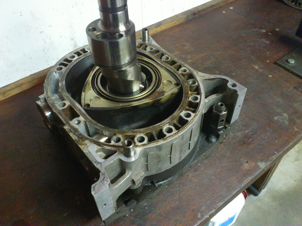
Here I was checking for any warpage of the housing, since they are heavily modified I was afraid that the material would disort a bit, but I couldn't find or measure any warping.
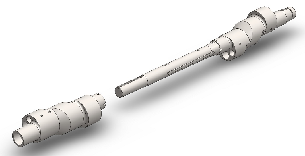
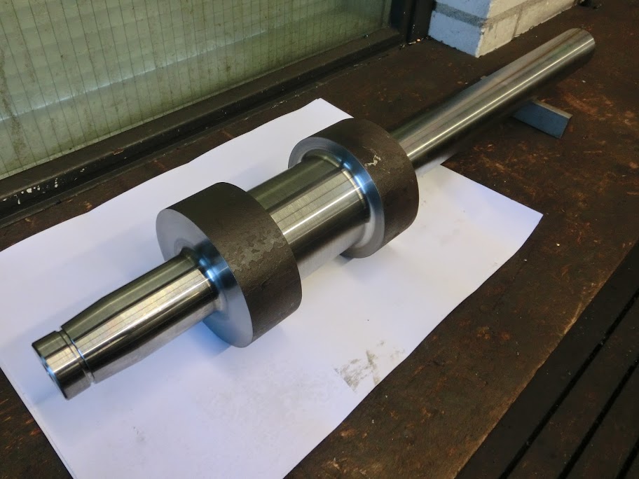
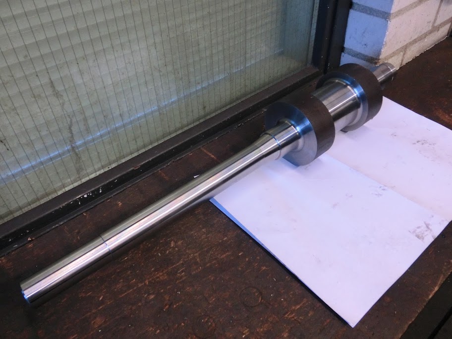
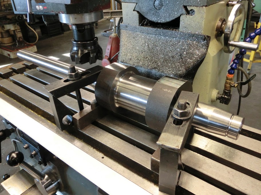
I also started on the eccentric shaft. I'm going to try making one myself, with my plain old manual lathe and mill.
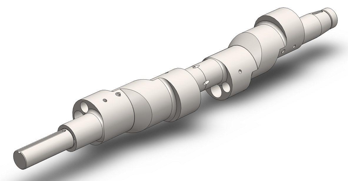
The design is a bit different from the regular designs. I've worked on this design for a few months, I've modelled and tested 4 different shafts on the computer, this design should be the strongest. It's also realatively easy to fabricate, and it's simpeler as it's a 2-piece design instead of a 3-piece. Only downside is that assembling the engine is more difficult. I basically have to assemble the rear engine first, with the rear iron, 1 regular intermediate iron and 1 modified intermediate iron. Then I have to assembly the front engine, with the front iron, and intermediate plate, with the hollow eccentric shaft piece, when that's done I should be able to join the 2 parts together by sliding the front part over the rear part.
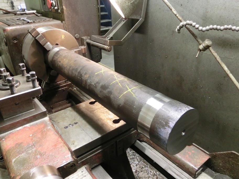
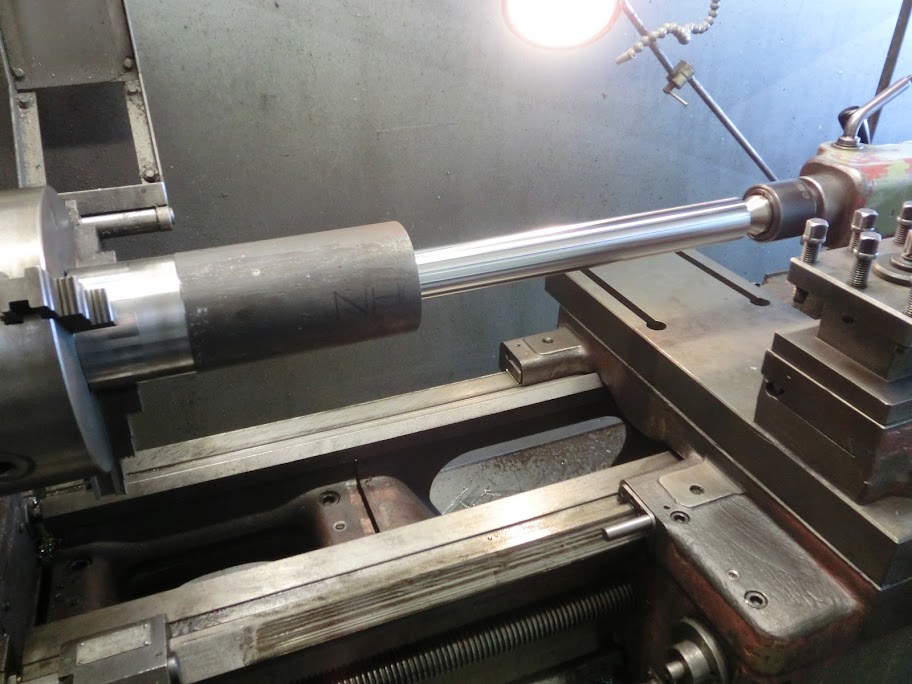
This is the start of the main eccentric shaft. I was boring centering holes here, which are to securely mount the roundbar in the lathe.
Here are the housings just before pressing in the inserts, they are a light pressfit. The waterchannel was "ported", the defcon will bond better this way.
With inserted inserts. I've put some devcon on the inserts before inserting, you can see some of it on the outside, this will help sealing.
Inlets, Outlets, plain and simple, I still need to fill up those air-emission hole things, mill the exhaust flange surface flat, and clean everything up.
Here I was checking for any warpage of the housing, since they are heavily modified I was afraid that the material would disort a bit, but I couldn't find or measure any warping.
I also started on the eccentric shaft. I'm going to try making one myself, with my plain old manual lathe and mill.
The design is a bit different from the regular designs. I've worked on this design for a few months, I've modelled and tested 4 different shafts on the computer, this design should be the strongest. It's also realatively easy to fabricate, and it's simpeler as it's a 2-piece design instead of a 3-piece. Only downside is that assembling the engine is more difficult. I basically have to assemble the rear engine first, with the rear iron, 1 regular intermediate iron and 1 modified intermediate iron. Then I have to assembly the front engine, with the front iron, and intermediate plate, with the hollow eccentric shaft piece, when that's done I should be able to join the 2 parts together by sliding the front part over the rear part.
This is the start of the main eccentric shaft. I was boring centering holes here, which are to securely mount the roundbar in the lathe.
Thread Starter
Member
Joined: Oct 2010
Posts: 34
From: Netherlands
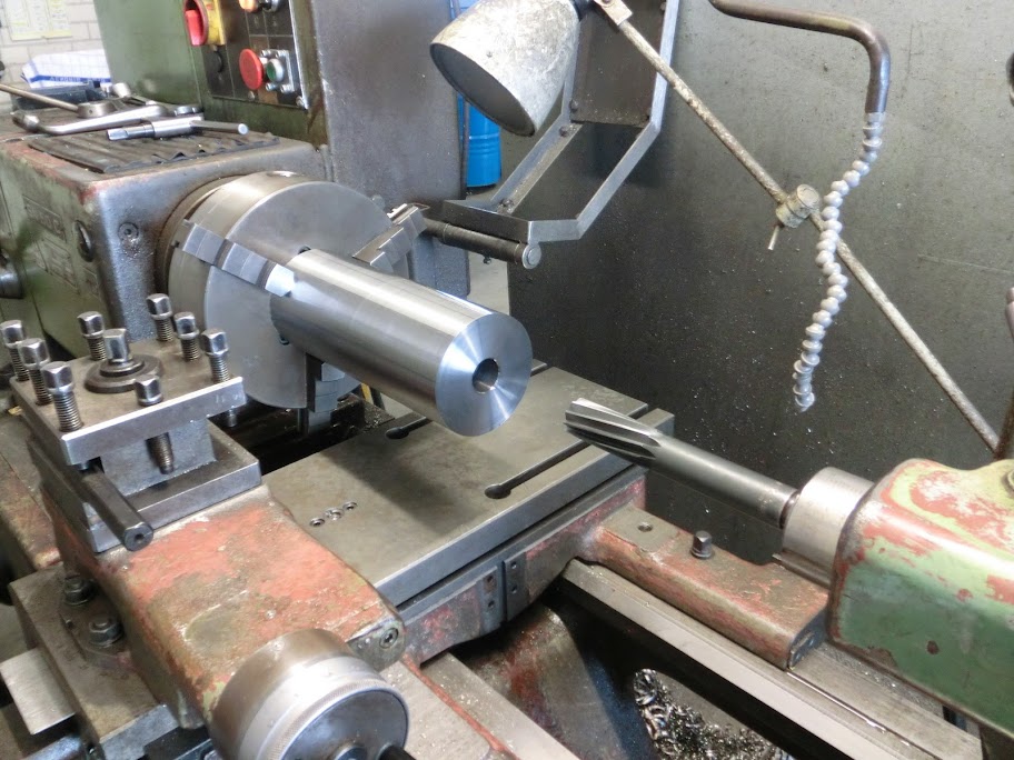
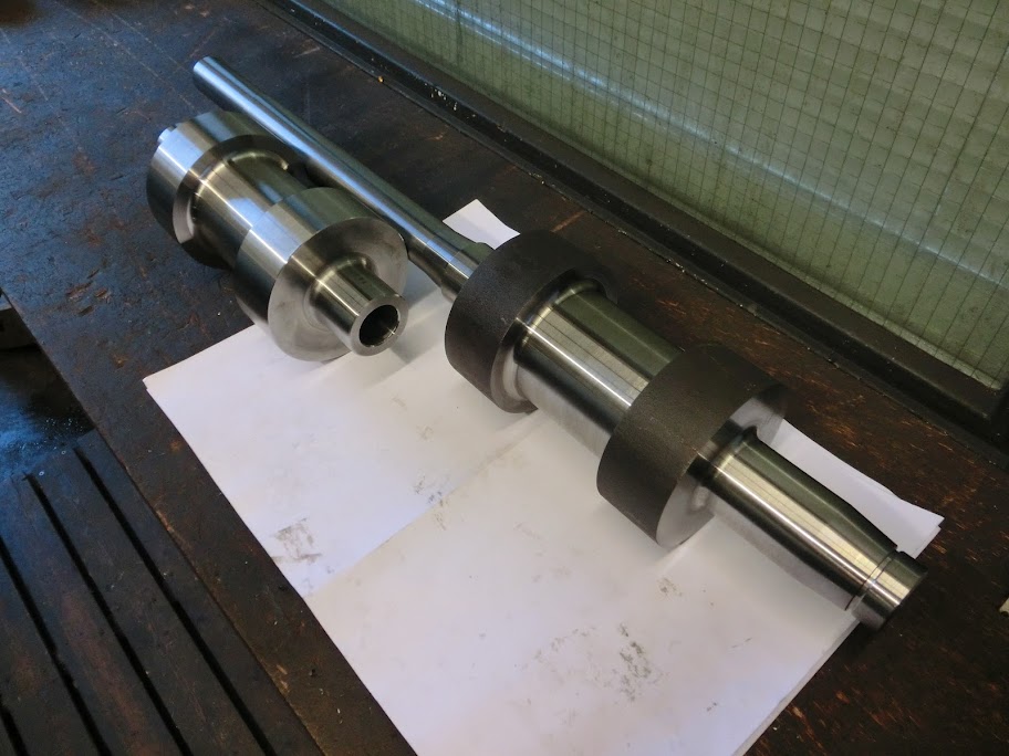
Roughturning the material, I started with a 125 pounds weighing slob of material. About 75 - 80% of the material ends up in the bin.
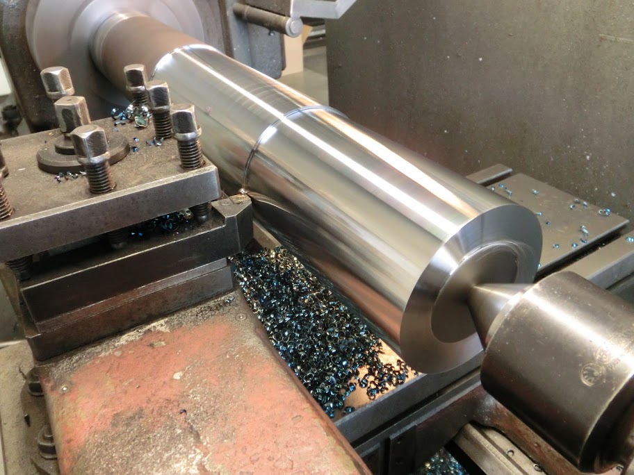
After an hour of turning
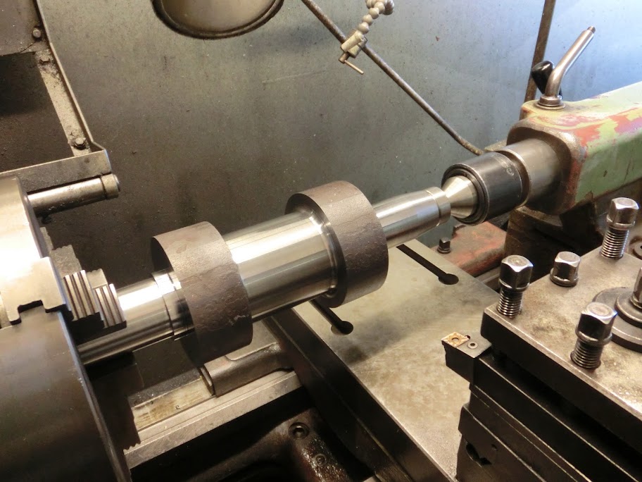
I flipped the shaft around and started on the other side, after machining:
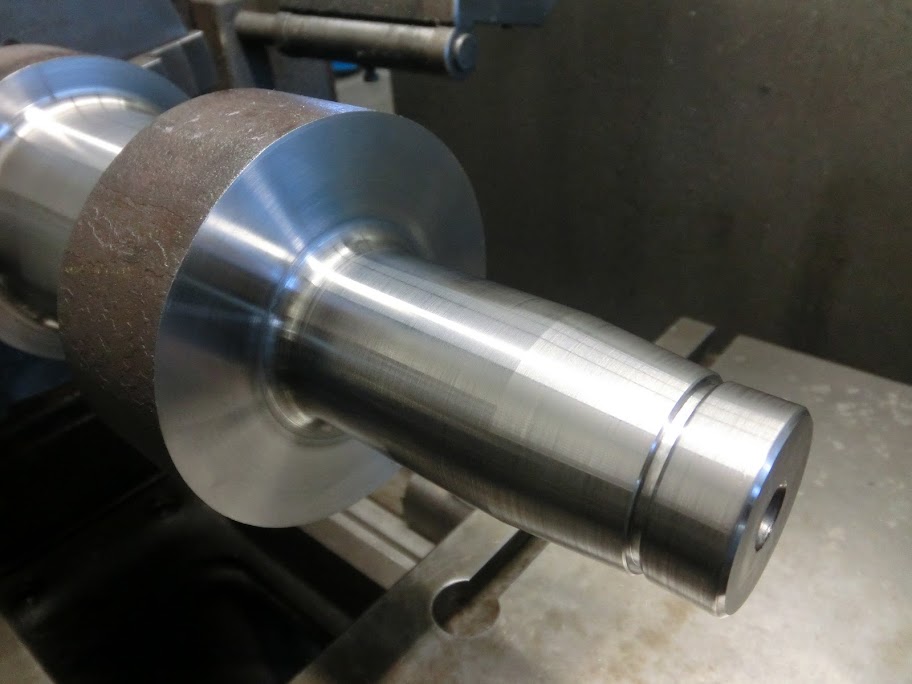
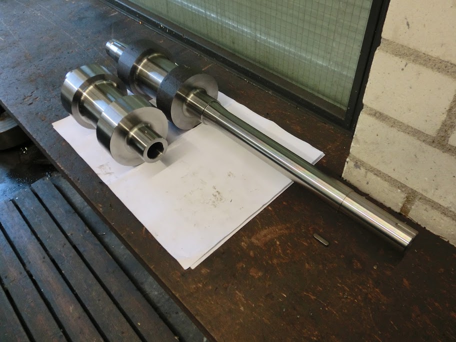
This is where I am at the moment.
Let me know if there are any questions
After an hour of turning
I flipped the shaft around and started on the other side, after machining:
This is where I am at the moment.
Let me know if there are any questions


Thread Starter
Member
Joined: Oct 2010
Posts: 34
From: Netherlands
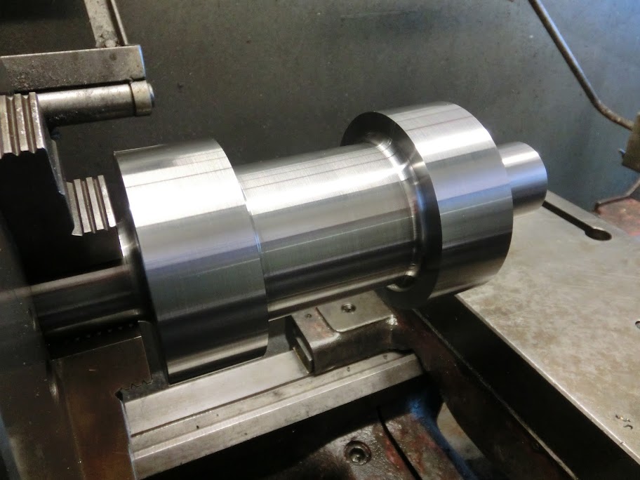
I made some progress on the e-shaft today.
First thing I did was finish turning the straight part of the main e-shaft.
After that was done I started on the slip-on piece. After some turning, drilling and reaming it looked like this:
After more turning:
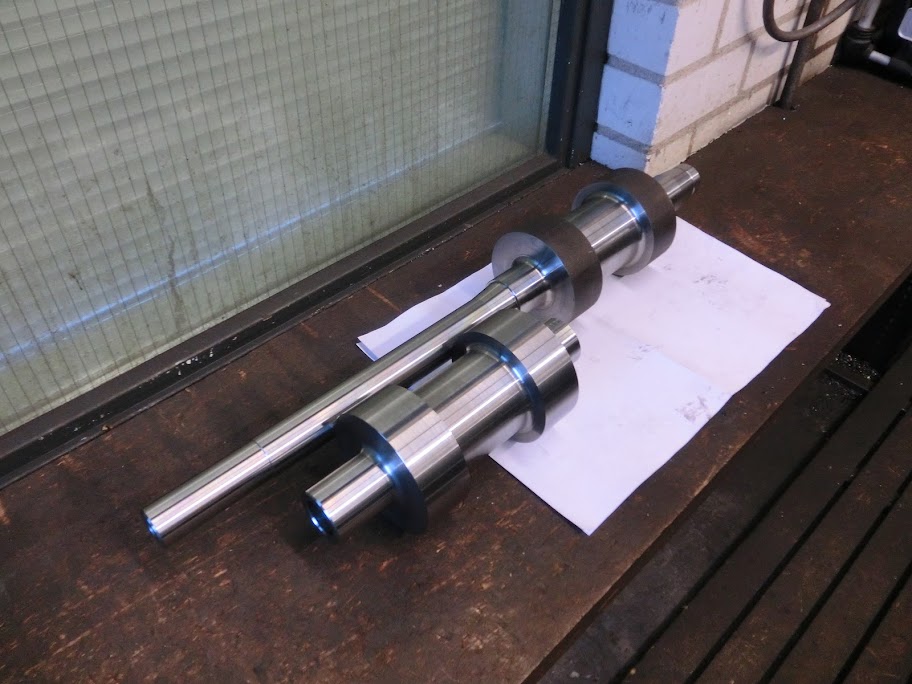
After turning the straight parts I needed to turn the eccentrical parts, where the rotors go.
To do this the shaft needs to be placed in the lathe eccentrically. Special care needs to be taken that the shaft is positioned correctly, there are a number of ways to do this. I decided to mill small locating slots and fabricate jigs to place the shaft in the lathe.
Placing the slip-on piece on the mill:
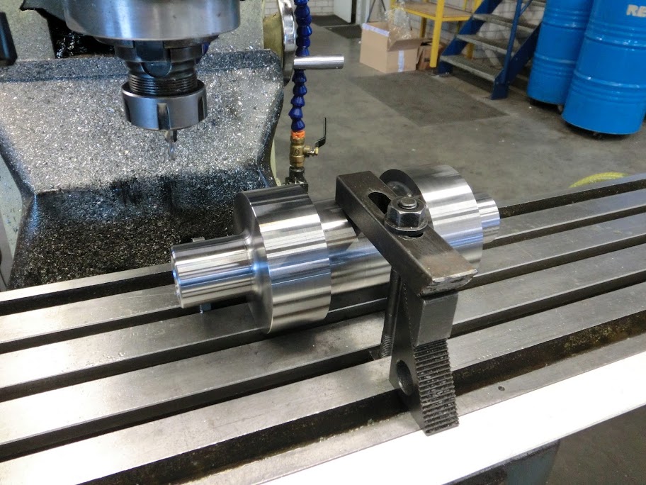
Then small keyways were milled
Astute readers will notice that the bearing surface gets ruined this way. No worries, the entire shaft is machined bigger than the final dimension, this is needed because the shaft will warp because of heat treatment. Therefore I left 2mm's of material in all diameters. The slots are only 1.2mm deep, so when the shaft gets machined after heat treating these slots will be removed.
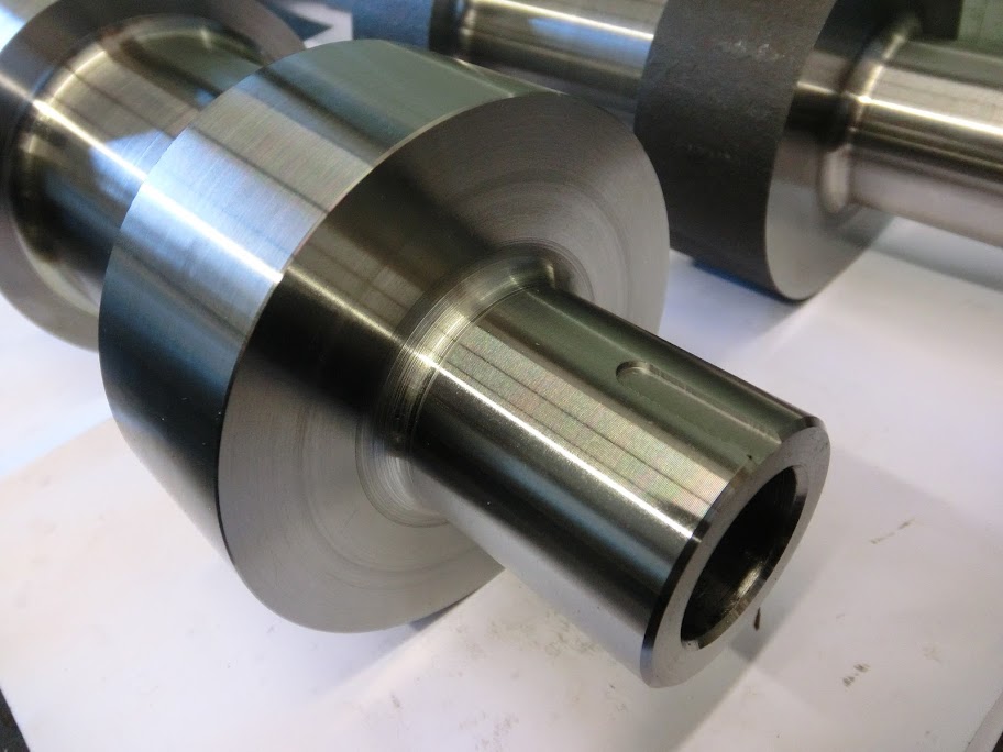
The e-shaft also needed these grooves, but the shaft is too long for my mill to machine both slots in one setup. Therefore I milled a flat surface and flipped the shaft over so it lays on the flat part. This way the indexing of both slots is identical.
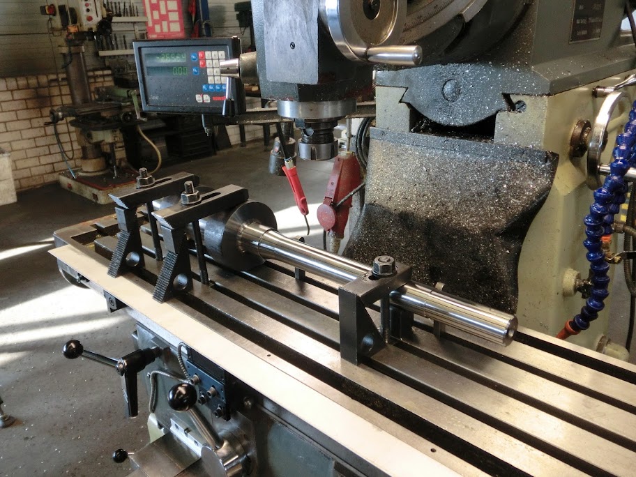
With machined keyways
Next job is fabricating jig's.
It's a lot of work, but the ending result should be worth it.
First thing I did was finish turning the straight part of the main e-shaft.
After that was done I started on the slip-on piece. After some turning, drilling and reaming it looked like this:
After more turning:
After turning the straight parts I needed to turn the eccentrical parts, where the rotors go.
To do this the shaft needs to be placed in the lathe eccentrically. Special care needs to be taken that the shaft is positioned correctly, there are a number of ways to do this. I decided to mill small locating slots and fabricate jigs to place the shaft in the lathe.
Placing the slip-on piece on the mill:
Then small keyways were milled
Astute readers will notice that the bearing surface gets ruined this way. No worries, the entire shaft is machined bigger than the final dimension, this is needed because the shaft will warp because of heat treatment. Therefore I left 2mm's of material in all diameters. The slots are only 1.2mm deep, so when the shaft gets machined after heat treating these slots will be removed.
The e-shaft also needed these grooves, but the shaft is too long for my mill to machine both slots in one setup. Therefore I milled a flat surface and flipped the shaft over so it lays on the flat part. This way the indexing of both slots is identical.
With machined keyways
Next job is fabricating jig's.
It's a lot of work, but the ending result should be worth it.

Member
Joined: Sep 2007
Posts: 60
From: Indianapolis
Excellent build! It's great to see what someone can do with some ingenuity and decent machine shop. I really like the exhaust inserts, but one question. What are you going to do for the primaries on the header? An oval to round transition out of the block and round primaries? I am planning a 13B peripheral port motor and like how clean your machining method was. Do you mind disclosing your port timing? Just curious.
Thread Starter
Member
Joined: Oct 2010
Posts: 34
From: Netherlands
Sure, These are the inside shapes and dimensions of my intake and exhaust ports:
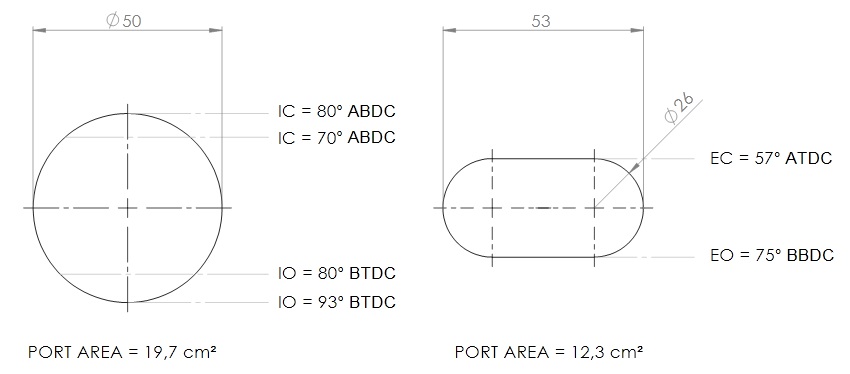
I drew in IC = 70� ABDC and IO = 80� BTDC to show that there isn't a lot of port area left when the rotor is beyond that timing. My port is perfectly roundshaped, a rectangular port with the same timings will act very different than this port. The reason I went with a round intake port is that it's a lot easier to fabricate, and should flow well in combination with a slide throttlebody mounted directly onto the housing. It's also puts less stress on the apex seals. I could've actually gone larger with the ports, I had more things to concider than just top end power alone so I settled on this. Nothing very special or anything, it's pretty similar to the ports that mazda have been using even before I was born. You should read SAE paper 900032, it has some good info on port timings.
As for the exhaust port shape, I decided to create an exhaust port channel that is entirely straight, so the part that you can see at the exhaust flange surface on the rotor housing is exactly like the drawing above. The airflow is very turbulent when it exits the combustion chamber. The idea I had behind it is that a straight flowing exhaust path that doesn't change in shape or dimension is the quickest way to change a turbulent flow into a laminar flow. laminar flow is a lot better than turbulent flow in terms of flow. It also keeps the velocity of the gases high. If you search around on the forum's you'll find a clear explanation by rotarygod, which has done basically the same with his engine. Difference is he used a straight formed insert, I made an entirely new exhaust channel.
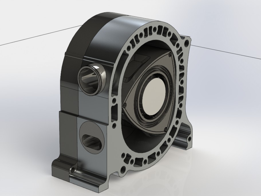
Here is the rotor housing with the exhaust channel in CAD:
I'm going to do round primary's, Planning on using a short system with 44,3mm ID primary's (1,75" that is), and a 4-1 collector.
The exhaust primary connection will probably look something like this (look at the light coloured dotted lines):
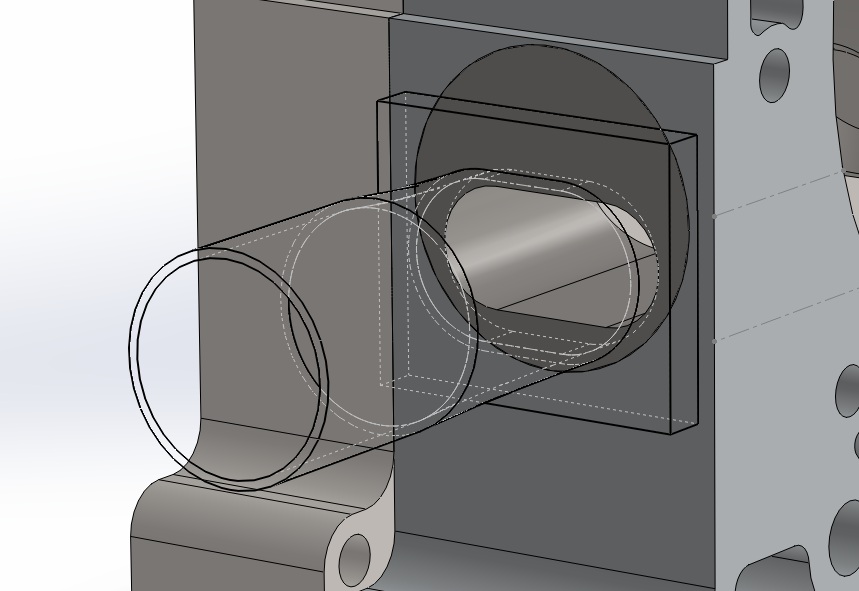
So basically I'll press a piece of pipe over a mould to form the ending into a wider and flatter shape, much like the exhaust channel shape, only a bit higher. This forms an anti-reversion lip, which should be good for performance. I've been doing the same thing to 2-strokes for ages. Flow should look something like this:
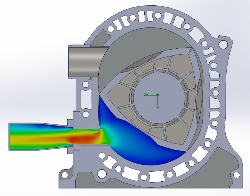
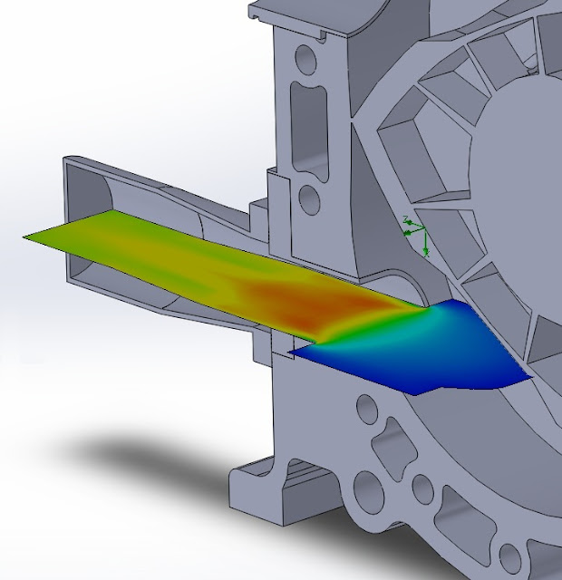
Don't pay a huge deal of attention to the flow pictures, I calculated most of the needed variables to perform the simulation, but it's probably not completely accurate since the flow of gasses in a rotary engine is just much more complex than this. I havent taken the exact movement of the flamefront in account. This is just a simulation of a certain gas with a given temperature and mass flow moving to a point with enviromental pressure through a rotary engine. Still interesting I think.
I drew in IC = 70� ABDC and IO = 80� BTDC to show that there isn't a lot of port area left when the rotor is beyond that timing. My port is perfectly roundshaped, a rectangular port with the same timings will act very different than this port. The reason I went with a round intake port is that it's a lot easier to fabricate, and should flow well in combination with a slide throttlebody mounted directly onto the housing. It's also puts less stress on the apex seals. I could've actually gone larger with the ports, I had more things to concider than just top end power alone so I settled on this. Nothing very special or anything, it's pretty similar to the ports that mazda have been using even before I was born. You should read SAE paper 900032, it has some good info on port timings.
As for the exhaust port shape, I decided to create an exhaust port channel that is entirely straight, so the part that you can see at the exhaust flange surface on the rotor housing is exactly like the drawing above. The airflow is very turbulent when it exits the combustion chamber. The idea I had behind it is that a straight flowing exhaust path that doesn't change in shape or dimension is the quickest way to change a turbulent flow into a laminar flow. laminar flow is a lot better than turbulent flow in terms of flow. It also keeps the velocity of the gases high. If you search around on the forum's you'll find a clear explanation by rotarygod, which has done basically the same with his engine. Difference is he used a straight formed insert, I made an entirely new exhaust channel.
Here is the rotor housing with the exhaust channel in CAD:
I'm going to do round primary's, Planning on using a short system with 44,3mm ID primary's (1,75" that is), and a 4-1 collector.
The exhaust primary connection will probably look something like this (look at the light coloured dotted lines):
So basically I'll press a piece of pipe over a mould to form the ending into a wider and flatter shape, much like the exhaust channel shape, only a bit higher. This forms an anti-reversion lip, which should be good for performance. I've been doing the same thing to 2-strokes for ages. Flow should look something like this:
Don't pay a huge deal of attention to the flow pictures, I calculated most of the needed variables to perform the simulation, but it's probably not completely accurate since the flow of gasses in a rotary engine is just much more complex than this. I havent taken the exact movement of the flamefront in account. This is just a simulation of a certain gas with a given temperature and mass flow moving to a point with enviromental pressure through a rotary engine. Still interesting I think.
