
Electronic Boost Controllor prototype V0.9


Thread Starter
Senior Member
Joined: Oct 2003
Posts: 714
From: WA, Renton
heres a couple sneak peek pics from my prototype electronic boost controllor i am working on
i got it working in the lab, but im so busy i might not test it on the vehicle for a couple weeks or so.
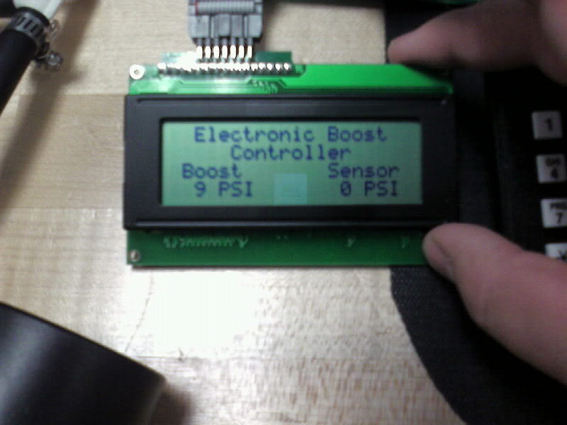
A pic of the display display limit on left, and sensor/gauge reading on the right
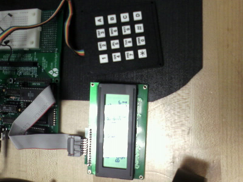
num pad for settinb boost level
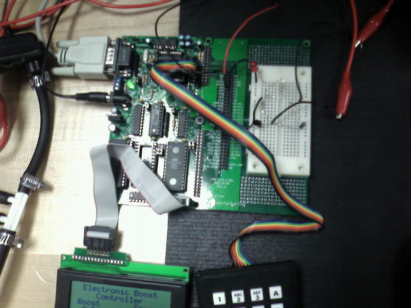
a pic of hte board
heres a pic of the hand pump we used to simulate the pressure.

what u guys think??
i got it working in the lab, but im so busy i might not test it on the vehicle for a couple weeks or so.
A pic of the display display limit on left, and sensor/gauge reading on the right
num pad for settinb boost level
a pic of hte board
heres a pic of the hand pump we used to simulate the pressure.
what u guys think??

Senior Member
Joined: May 2005
Posts: 446
From: central WA state
heres a pic of the hand pump we used to simulate the pressure.
what u guys think??
[/quote]
i think your hand is going to get really sore developing enough boost to gain any performance over the na...
unlessn you have had a lot of practice.
what u guys think??
[/quote]
i think your hand is going to get really sore developing enough boost to gain any performance over the na...
unlessn you have had a lot of practice.

Senior Member
Joined: Jan 2003
Posts: 260
Originally Posted by jenkin' post='841541' date='Oct 19 2006, 08:55 AM
i think your hand is going to get really sore developing enough boost to gain any performance over the na...
unlessn you have had a lot of practice.
bwahahahah!


Senior Member
Joined: Mar 2003
Posts: 422
From: from spokane, now a west sider...
Originally Posted by rmriggin' post='841666' date='Oct 19 2006, 05:27 PM
Let us know when you get a parts list and some directions put together. Looking good. I would be interested in doing this because I got an extra 4 row LCD laying around.
Thread Starter
Senior Member
Joined: Oct 2003
Posts: 714
From: WA, Renton
Originally Posted by rmriggin' post='841666' date='Oct 19 2006, 05:27 PM
Let us know when you get a parts list and some directions put together. Looking good. I would be interested in doing this because I got an extra 4 row LCD laying around.
This is a prototype version and the parts used are quite expensive... theres also a fair amount of coding involved...
i am planning on designing a cheaper version using a more compact microcontrollor that doesnt have an overkill of features...
and then i plan to sell a few of them posibily

Thread Starter
Senior Member
Joined: Oct 2003
Posts: 714
From: WA, Renton
Originally Posted by Codeblue' post='841698' date='Oct 19 2006, 06:59 PM
I do need a boost controllor. you can send me one to try out.
And i will work out the bugs. How many wires are there going to be ?
well its still months away from a consumer testable one, besides the single one i have, wires will be ground and 12V , then wires to run to the sensor and solinoid

Senior Member
Joined: Jan 2006
Posts: 545
Originally Posted by KompressorLOgic' post='841730' date='Oct 19 2006, 09:10 PM
well its still months away from a consumer testable one, besides the single one i have, wires will be ground and 12V , then wires to run to the sensor and solinoid
Bull. You will have this boost controller in you car before the next Izzy's,