
Can anyone help?


Thread Starter
Junior Member
Joined: Feb 2011
Posts: 3
From: Okinawa Japan
So I just picked this up today for my FD. Couldnt really find anything as far as support or wiring writeups go being I think this is an older model. FYI this is going into a FD with a streetported 13b, 62-1 turbo, power FC with all supporting mods such as 1680 pri and 550 secs ect ect... I have a couple questions as far as how the heck-a-daisy I hook this thing up.
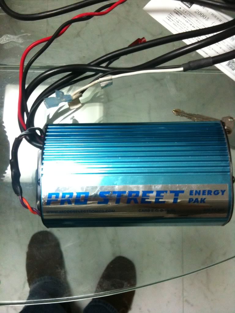
What I bought, big *****
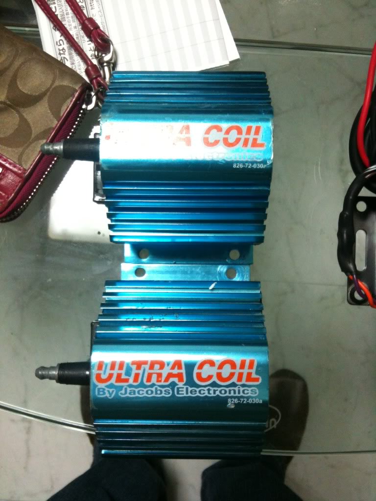
First, is this how it comes from the factory? Seems odd to me
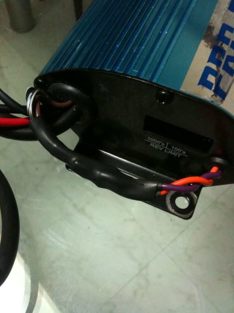
Second, the red and green are coming from ignition box, red and purple I dont know if it came like that, or someone had hooked it up before
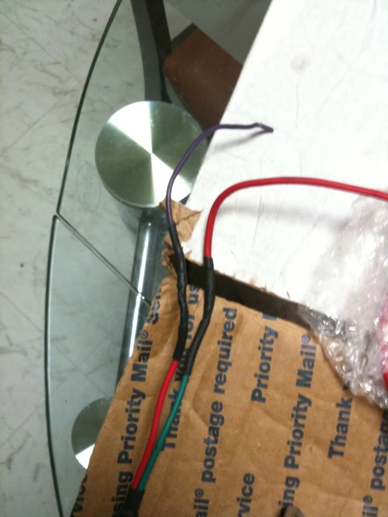
Third is these short wires coming out of the ign.
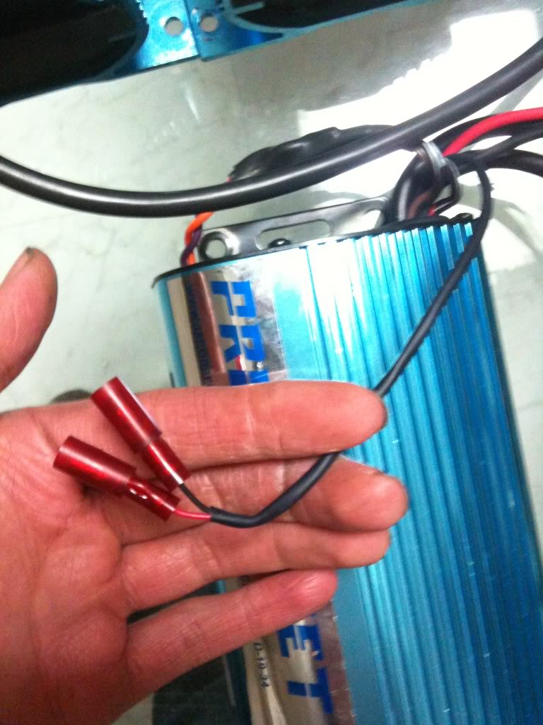
Forth is the coil wires, obviously they hook up + and - to the coil, but I have two, soooo how does this get wired in since I will have two coils being ran by this and only 1 set of wires that have + and - coil markings
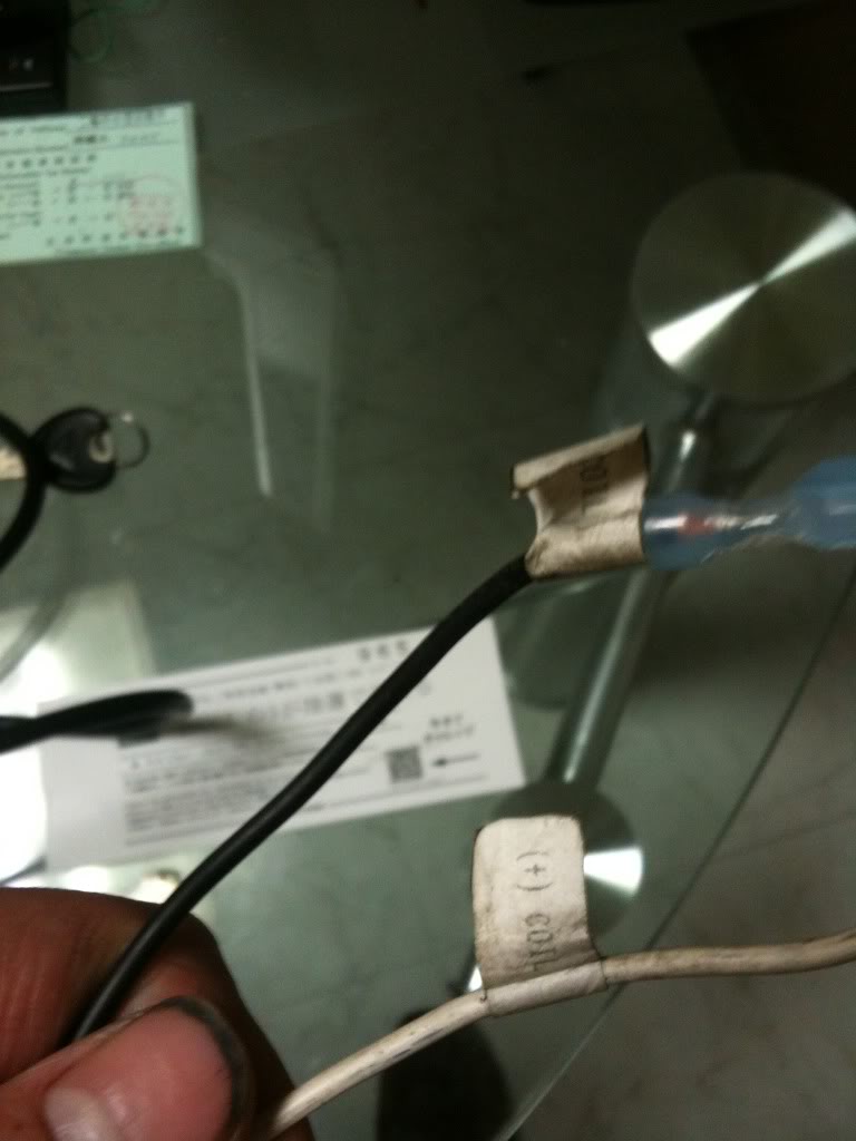
sorry if this is all hard to understand, little bit spaced out from the vicaden Im on right now
What I bought, big *****
First, is this how it comes from the factory? Seems odd to me
Second, the red and green are coming from ignition box, red and purple I dont know if it came like that, or someone had hooked it up before
Third is these short wires coming out of the ign.
Forth is the coil wires, obviously they hook up + and - to the coil, but I have two, soooo how does this get wired in since I will have two coils being ran by this and only 1 set of wires that have + and - coil markings
sorry if this is all hard to understand, little bit spaced out from the vicaden Im on right now

Senior Member
Joined: Dec 2003
Posts: 791
From: Mid-West
I have no experience with amplifiers or aftermarket coils. From what I understand though, not all of them work well with FI rotories, so if you haven't already, you might want to do some research.
In any event, this might have something that can help. They do show the PRO STREET, but two different part numbers.....
http://www.accel-ignition.com/Instru...List.aspx?b2=j
In any event, this might have something that can help. They do show the PRO STREET, but two different part numbers.....
http://www.accel-ignition.com/Instru...List.aspx?b2=j

Senior Member
Joined: Nov 2009
Posts: 1,833
From: peru, IN
Yeah, accel bought out jakobs so it's real hard to come by directions for them. From my own research it seems as though you need to hook up the amplifier on the leading side since they fire together. You unhook the stock leading coil input wires from the ignitor and splice them to the signal wires of the amp. The output wires then go to your coil(s) and connect your plug wires. I believe the amp has a power wire to go to the battery and the amp's body grounds to the car's frame when you mount it.
This is just how I understand the system but I still have yet to figure it out. Previous owner installed a jakobs amp but spliced Ito wires from the harness so I really have no idea what he did, but my trailing plugs never fire. I'm as interested as you in finding out what to do with this thing lol
This is just how I understand the system but I still have yet to figure it out. Previous owner installed a jakobs amp but spliced Ito wires from the harness so I really have no idea what he did, but my trailing plugs never fire. I'm as interested as you in finding out what to do with this thing lol
Thread Starter
Junior Member
Joined: Feb 2011
Posts: 3
From: Okinawa Japan
Yeah, accel bought out jakobs so it's real hard to come by directions for them. From my own research it seems as though you need to hook up the amplifier on the leading side since they fire together. You unhook the stock leading coil input wires from the ignitor and splice them to the signal wires of the amp. The output wires then go to your coil(s) and connect your plug wires. I believe the amp has a power wire to go to the battery and the amp's body grounds to the car's frame when you mount it.
This is just how I understand the system but I still have yet to figure it out. Previous owner installed a jakobs amp but spliced Ito wires from the harness so I really have no idea what he did, but my trailing plugs never fire. I'm as interested as you in finding out what to do with this thing lol
This is just how I understand the system but I still have yet to figure it out. Previous owner installed a jakobs amp but spliced Ito wires from the harness so I really have no idea what he did, but my trailing plugs never fire. I'm as interested as you in finding out what to do with this thing lol
Ah, so the leading plugs fire togeather correct? Thats the main thing I was wondering since I am gonna run 1 coil per rotor, guess then I just have to splice out another wire from each coil wire?
Senior Member
Joined: Nov 2009
Posts: 1,833
From: peru, IN
Ok after a quick browse it's the leadings that fire together and trappings fire separately (now I know why my car runs so poorly lol the brown wire coming from the ignitor is for the front trailing coil signal. Grey is for the rear trailing rotor. I'd switch over to the schematic to check the other wire colors, but pdf's take awhile to download on an iPhone lol in the fd fsm in the engine electrical system section pages g16-g23 are what I referenced
As far as your amp, I'd hook it up on the leading side. On page g16 if you look at the mini schematic, you can see that wire A on the leading coil is the power. That's what you'll want to run to the amp as the signal (+) wire. Coming from the ignitor is wire B. The computer tells the ignitor when to fire, then the ignitor uses a couple diodes to close the circuit to ground. This will be your signal (-) wire or coil ground, depending on who wrote your directions will depend on what they call it. You can run individual coils for the leadings by splitting the wires going from the amp to the coils. As for the trailings, use individual coils with the original wires run to them from the ignitor or run them to individual amps for those coils if you so choose to spend a ton of money. Unless you're planning on adding several extra injectors and pumping in by the gallon, you really shouldn't need that much firepower
Hope this helped
Thread Starter
Junior Member
Joined: Feb 2011
Posts: 3
From: Okinawa Japan
Ok after a quick browse it's the leadings that fire together and trappings fire separately (now I know why my car runs so poorly lol the brown wire coming from the ignitor is for the front trailing coil signal. Grey is for the rear trailing rotor. I'd switch over to the schematic to check the other wire colors, but pdf's take awhile to download on an iPhone lol in the fd fsm in the engine electrical system section pages g16-g23 are what I referenced As far as your amp, I'd hook it up on the leading side. On page g16 if you look at the mini schematic, you can see that wire A on the leading coil is the power. That's what you'll want to run to the amp as the signal (+) wire. Coming from the ignitor is wire B. The computer tells the ignitor when to fire, then the ignitor uses a couple diodes to close the circuit to ground. This will be your signal (-) wire or coil ground, depending on who wrote your directions will depend on what they call it. You can run individual coils for the leadings by splitting the wires going from the amp to the coils. As for the trailings, use individual coils with the original wires run to them from the ignitor or run them to individual amps for those coils if you so choose to spend a ton of money. Unless you're planning on adding several extra injectors and pumping in by the gallon, you really shouldn't need that much firepower Hope this helped
Senior Member
Joined: Nov 2009
Posts: 1,833
From: peru, IN
Lol no problem. The reason for the ignition working like that is that the leadings are just supposed to get the rotor started going in the right direction, the trailings fire to complete combustion and add power

Thread
Thread Starter
Forum
Replies
Last Post
Currently Active Users Viewing This Thread: 1 (0 members and 1 guests)